
Page 197 - Petroleum Production Engineering, A Computer-Assisted Approach
P. 197
Guo, Boyun / Computer Assited Petroleum Production Engg 0750682701_chap13 Final Proof page 193 3.1.2007 9:07pm Compositor Name: SJoearun
GAS LIFT 13/193
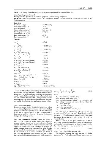
Table 13.3 Result Given by the Computer Program CentrifugalCompressorPower.xls
CentrifugalCompressorPower.xls
Description: This spreadsheet calculates stage power of reciprocating compressor.
Instruction: (1) Update parameter valves in the ‘‘Input data’’ in blue; (2) click ‘‘Solution’’ button; (3) view result in the
Solution section.
Input data
Gas flow rate (q g ): 32 MMscf/day
Inlet temperature (T 1 ): 70 8F
Inlet pressure ( p 1 ): 100 psia
Gas-specific gravity (g g ): 0:65 (air ¼ 1)
Discharge pressure ( p 2 ): 341 psia
Gas-specific heat ratio (k): 1.25
Base temperature (T b ): 60 8F
Base pressure ( p b ): 14.7 psia
Solution
p 2
r ¼ ¼ 3:41
p 1
q MM
q ¼ ¼ 22,222 scfm
(24)(60)
p b T 1
q 1 ¼ q ¼ 3,329 scfm
p 1 T b
E p ¼ 0:61 þ 0:03 log (q 1 ) ¼ 0:7192
n 1 k 1 1
R p ¼ ¼ ¼ 0:2781
n k E p
T 2 ¼ T 1 r R p ¼ 285 F
z 1 by Hall–Yarborogh Method ¼ 1:0891
z 2 by Hall–Yarborogh Method ¼ 0:9869
z 1 p b T 1
q 1 ¼ q ¼ 3,674
z 2 p 1 T b
E p ¼ 0:61 þ 0:03 log (q 1 ) ¼ 0:7205
n 1 k 1 1
R p ¼ ¼ ¼ 0:2776
n k E p
T 2 ¼ T 1 r R p ¼ 285 F
q 1 p 1 z 1 þ z 2 r R p 1
Hp g ¼ ¼ 3,102 hp
229E p 2z 1 R p
Hp b ¼ Hp g þ 50 ¼ 3,152 hp
¼ 18:85
MW a ¼ 29g g
R ¼ 1,544 ¼ 81:91
MW a
z 1 þz 2 r Rp 1
H g ¼ RT 1 2 R p ¼ 65,853 lbf-ft=lbm
1 R
There are different types of unloading valves, namely casing P vo ¼ P d þ S t P t , (13:42)
pressure-operated valve (usually called a pressure valve), throt- 1 R 1 R
tling pressure valve (also called a proportional valve or continu- where
ous flow valve), fluid-operated valve (also called a fluid valve),
P vo ¼ valve opening pressure, psig
and combination valve (also called a fluid open-pressure closed
P d ¼ pressure in the dome, psig
valve). Different gas lift design methods have been developed
S t ¼ equivalent pressure caused by spring tension, psig
and used in the oil industry for applications of these valves.
P t ¼ tubing pressure at valve depth when the
valve opens, psi
13.5.2.1 Pressure Valve R ¼ area ratio A p =A b
Pressure valves are further classified as unbalanced bellow A p ¼ valve seat area, in: 2
2
valves, balanced pressure valves, and pilot valves. Tubing A b ¼ total effective bellows area, in: .
pressure affects the opening action of the unbalanced R R
valves, but it does not affect the opening or closing of The term 1 R P t is called tubing effect (T.E.) and 1 R
balanced valves. Pilot valves were developed for intermit- is called tubing effect factor (T.E.F.). With other parameters
tent gas lift with large ports. given, Eq. (13.42) is used for determining the required dome
pressure at depth, that is, P d ¼ (1 R)P vo S t þ RP t ,in
13.5.2.1.1 Unbalanced Bellow Valve As shown in valve selection.
Fig. 13.9, an unbalanced bellow valve has a pressure- When a valve is at its open condition (as shown in
charged nitrogen dome and an optional spring loading Fig. 13.10), the maximum pressure under the ball (assumed
element. While the forces from the dome pressure and spring to be casing pressure) required to close the valve is called
act to cause closing of the valve, the forces due to casing and the valve closing pressure and is expressed as
tubing pressures act to cause opening of the valve. Detailed P vc ¼ P d þ S t 1 Rð Þ, (13:43)
discussions of valve mechanics can be found in Brown (1980).
When a valve is at its closed condition (as shown in where P vc ¼ valve closing pressure, psig.
Fig. 13.9), the minimum casing pressure required to open The difference between the valve opening and closing
the valve is called the valve opening pressure and is expressed as pressures,P vo P vc ,iscalledspread.Spreadcanbeimportant