Page 202 - Petroleum Production Engineering, A Computer-Assisted Approach
P. 202

Guo, Boyun / Computer Assited Petroleum Production Engg 0750682701_chap13 Final Proof page 198  3.1.2007 9:07pm Compositor Name: SJoearun


               13/198  ARTIFICIAL LIFT METHODS
                                                         Detailed descriptions of these procedures are given by
                                                         Brown (1980). Only the design procedure using constant
                                                         surface opening pressure for pressure-operated valves is
                                                         illustrated in this section.
                                                          Figure 13.18 illustrates a graphical solution procedure
                        P t                              of valve spacing using constant surface opening pressure
                                                         for pressure-operated valves. The arrows in the figure
                                                         depict the sequence of line drawing.
                                                          For a continuous-flow gas lift, the analytical solution
                                            A p
                                                         procedure is outlined as follows:
                                            P c
                                                         1. Starting from a desired wellhead pressure p hf at surface,
                                                           compute a flowing tubing-pressure traverse under fully
                                              Small orifice
                                                           unloaded condition. This can be done using various two-
                                                           phase flow correlations such as the modified Hagedorn–
                                                S t        Brown correlation (HagedornBrownCorrelation.xls).
                                                         2. Starting from a design wellhead pressure p hf,d ¼ p hf
                                                           þ Dp hf,d at surface, where Dp hf can be taken as
                                                           0:25p c,s establish a design tubing line meeting the flow-
                                                           ing tubing-pressure traverse at tubing shoe. Pressures in
                                                           this line, denoted by p td , represent tubing pressure after
                                              A p          adjustment for tubing pressure margin. Gradient of this
                                                           line is denoted by G fd . Set Dp hf ¼ 0 if tubing pressure
                                                           margin is not required.
                                                         3. Starting from a desired injection operating pressure p c
                                                           at surface, compute a injection operating pressure line.
                                                           This can be done using Eq. (13.7) or Eq. (13.9).
                                              P c        4. Starting from p cs   Dp cm at surface, where the casing
                                                           pressure margin Dp cm can be taken as 50 psi, establish a
                  Figure 13.16 A sketch of a differential valve.  design casing line parallel to the injection operating
                                                           pressure line. Pressures in this line, denoted by p cd ,
                                                           represent injection pressure after adjustment for casing
               c. Design procedure for fluid-operated valves.  pressure margin. Set Dp cm ¼ 0 if the casing pressure
               d. Design procedure for combination of pressure-closed  margin is not required as in the case of using the
                 fluid-opened values.                      universal design method.
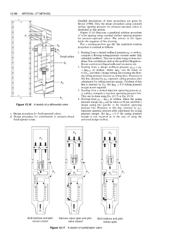


                                                      P d                   P d

                                 P d
                                                      A b                   A b
                                A b


                                         P                    P                     P
                                P t       c           P c      c            P c      c


                                 P t                  P t
                          Both bellows and pilot  Bellows valve open and pilot  Both bellows and pilot
                             valves closed         valve closed         valves open
                                       Figure 13.17 A sketch of combination valve.
   197   198   199   200   201   202   203   204   205   206   207