
Page 203 - Petroleum Production Engineering, A Computer-Assisted Approach
P. 203
Guo, Boyun / Computer Assited Petroleum Production Engg 0750682701_chap13 Final Proof page 199 3.1.2007 9:07pm Compositor Name: SJoearun
GAS LIFT 13/199
Pressure where
p p
p hf hf,d p c,s k,s
p cd2 ¼ design injection pressure at valve 2, psig
G fd ¼ design unloading gradient, psi/ft.
Kick-off Applying Eq. (13.9) gives
G s
Gf G f,d Pressure D 2
p cd2 ¼ p c,s Dp cm 1 þ : (13:52)
40,000
Solving Eqs. (13.51) and (13.52) yields
G s
∆p p c,s Dp cm p hf,d þ G s G fd D 1
∆p tm km D 2 ¼ G s p c Dp cm : (13:53)
Depth G s ∆p cm Similarly, the depth to the third valve is
40,000
G s
p c,s Dp cm p hf,d þ G s G fd D 2
D 3 ¼ (13:54)
p c Dp cm
G s :
G s
40,000
Operating Tubing G s Injection Operating Thus, a general equation for depth of valve i is
Pressure Pressure
p c,s Dp cm p hf,d þ G s G fd D i 1
D i ¼ (13:55)
G s
p c Dp cm
G s :
40,000
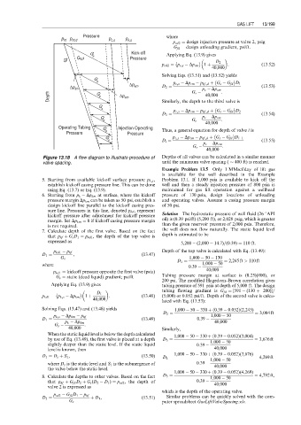
Figure 13.18 A flow diagram to illustrate procedure of Depths of all valves can be calculated in a similar manner
valve spacing. until the minimum valve spacing ( 400 ft) is reached.
Example Problem 13.5 Only 1 MMscf/day of lift gas
is available for the well described in the Example
5. Starting from available kickoff surface pressure p k,s , Problem 13.1. If 1,000 psia is available to kick off the
establish kickoff casing pressure line. This can be done well and then a steady injection pressure of 800 psia is
using Eq. (13.7) or Eq. (13.9). maintained for gas lift operation against a wellhead
6. Starting from p k Dp km at surface, where the kickoff pressure of 130 psia, design locations of unloading
pressure margin Dp km can be taken as 50 psi, establish a and operating valves. Assume a casing pressure margin
design kickoff line parallel to the kickoff casing pres- of 50 psi.
sure line. Pressures in this line, denoted p kd , represent
kickoff pressure after adjustment for kickoff pressure Solution The hydrostatic pressure of well fluid (26 8API
margin. Set Dp km ¼ 0 if kickoff casing pressure margin oil) is (0.39 psi/ft) (5,200 ft), or 2,028 psig, which is greater
is not required. than the given reservoir pressure of 2,000 psia. Therefore,
7. Calculate depth of the first valve. Based on the fact the well does not flow naturally. The static liquid level
that p hf þ G s D 1 ¼ p kd1 , the depth of the top valve is depth is estimated to be
expressed as
5,200 (2,000 14:7)=(0:39) ¼ 110 ft:
Depth of the top valve is calculated with Eq. (13.49):
p kd1 p hf
D 1 ¼ , (13:47)
G s 1,000 50 130
D 1 ¼ ¼ 2,245 ft > 110 ft
where 0:39 1,000 50
p kd1 ¼ kickoff pressure opposite the first valve (psia) 40,000
G s ¼ static (dead liquid) gradient; psi/ft Tubing pressure margin at surface is (0.25)(800), or
200 psi. The modified Hagedorn–Brown correlation gives
Applying Eq. (13.9) gives tubing pressure of 591 psia at depth of 5,000 ft. The design
tubing flowing gradient is G fd ¼ [591 (130 þ 200)]=
D 1
p kd1 ¼ p k,s Dp km 1 þ : (13:48) (5,000) or 0.052 psi/ft. Depth of the second valve is calcu-
40,000 lated with Eq. (13.53):
Solving Eqs. (13.47) and (13.48) yields 1,000 50 330 þ 0:39 0:052Þ(2,245)
ð
D 2 ¼ ¼ 3,004 ft
p k,s Dp km p hf 1,000 50
D 1 ¼ (13:49) 0:39
p k Dp km 40,000
G s :
40,000 Similarly,
When the static liquid level is below the depth calculated 1,000 50 330 þ 0:39 0:052Þ(3,004)
ð
by use of Eq. (13.49), the first valve is placed at a depth D 3 ¼ 1,000 50 ¼ 3,676 ft
slightly deeper than the static level. If the static liquid 0:39
level is known, then 40,000
ð
D 1 ¼ D s þ S 1 , (13:50) D 4 ¼ 1,000 50 330 þ 0:39 0:052Þ(3,676) ¼ 4,269 ft
1,000 50
where D s is the static level and S 1 is the submergence of 0:39 40,000
the valve below the static level.
ð
1,000 50 330 þ 0:39 0:052Þ(4,269)
8. Calculate the depths to other valves. Based on the fact D 5 ¼ 1,000 50 ¼ 4,792 ft,
that p hf þ G fd D 2 þ G s (D 2 D 1 ) ¼ p cd2 , the depth of 0:39 40,000
valve 2 is expressed as
which is the depth of the operating valve.
p cd2 G fd D 1 p hf
D 2 ¼ þ D 1 , (13:51) Similar problems can be quickly solved with the com-
G s puter spreadsheet GasLiftValveSpacing.xls.