
Page 207 - Petroleum Production Engineering, A Computer-Assisted Approach
P. 207
Guo, Boyun / Computer Assited Petroleum Production Engg 0750682701_chap13 Final Proof page 203 3.1.2007 9:07pm Compositor Name: SJoearun
GAS LIFT 13/203
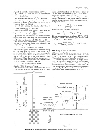
Figure 13.21 shows the example well and the WFL. injection depth to surface, less the volume occupied by
ð
The number of cycles per day is approximately the slug. Thus, this volume is 6,140 þ 1,292Þ 0:00387 ¼
3
ð
24 60Þ 18:8 bbls, which converts to 105:5ft .
¼ 32 cycles/day.
45 100 The approximate pressure in the tubing immediately
The number of bbls per cycle is 3 bbls=cycle. under a liquid slug at the instant the slug surfaces is
32 equal to the pressure due to the slug length plus the tubing
Intermittent-gas lift operating experience shows that
depending on depth, 30–60% of the total liquid slug is backpressure. This is
lost due to slippage or fallback. 3:0
If a 40% loss of starting slug is assumed, the volume of p ts ¼ 50 þ ð 0:379Þ ¼ 344 psig:
3 0:00387
the starting slug is 5:0 bbl=cycle.
0:60 Thus, the average pressure in the tubing is
Because the capacity of our tubing is 0.00387 bbl/ft, the
5:0 810 þ 344
length of the starting slug is 1,292 ft. p tave ¼ ¼ 577 psig ¼ 591:7 psia:
0:00387 2
This means that the operating valve should be located
1,292 The average temperature in the tubing is 127 8F or 587 8R.
¼ 646 ft below the working fluid level. Therefore, the This gives z ¼ 0:886. The volume of gas at standard condi-
2
depth to the operating valve is 5,494 þ 646 ¼ 6,140 ft. tions (API 60 8F, 14.695 psia) is
The pressure in the tubing opposite the operating valve
with the 50 psig surface back-pressure (neglecting the V sc ¼ 105:5 591:7 520 1 ¼ 4,246 scf=cycle:
weight of the gas column) is 14:695 587 0:886
p t ¼ 50 þ 1,292ð Þ 0:379Þ ¼ 540 psig:
ð
For minimum slippage and fallback, a minimum velocity
of the slug up the tubing should be 100 ft/min. This is 13.7 Design of Gas Lift Installations
accomplished by having the pressure in the casing opposite Different types of gas lift installations are used in the in-
the operating valve at the instant the valve opens to be at dustry depending on well conditions. They fall into four
least 50% greater than the tubing pressure with a minimum categories: (1) open installation, (2) semiclosed installation,
differential of 200 psi. Therefore, for a tubing pressure at (3) closed installation, and (4) chamber installation.
the valve depth of 540 psig, at the instant the valve opens, As shown in Fig. 13.22a, no packer is set in open installa-
the minimum casing pressure at 6,140 ft is tions. This type of installation is suitable for continuous flow
gas lift in wells with good fluid seal. Although this type of
p min c ¼ 540 þ 540=2 ¼ 810 psig:
installation is simple, it exposes all gas lift valves beneath the
Equation (13.10) gives a p so ¼ 707 psig. pointofgasinjectiontoseverefluiderosionduetothedynamic
The minimum volume of gas required to lift the slug to changing of liquid level in the annulus. Open installation is not
the surface will be that required to fill the tubing from recommended unless setting packer is not an option.
SFL = 2855 SFL BHPS = 2000PSIG
Depth to operating valve = 6140’ WFL = 5494’ 1993’ P = 755PSI Pressure build-up curve AVG DD = 1000PSI
Slug surfacing
8000’ Max working Valve 755PSI
opens
BHP=1245PSIG
AVG Working
1292’ P = 490PSI WFL BHP=1000PSIG 245PSI 490PSI
646’ MIN Working
BHP=755PSIG
45MIN 45MIN
Bottom hole pressure
Time
Figure 13.21 Example Problem 13.8 schematic and BHP buildup for slug flow.