
Page 204 - Petroleum Production Engineering, A Computer-Assisted Approach
P. 204
Guo, Boyun / Computer Assited Petroleum Production Engg 0750682701_chap13 Final Proof page 200 3.1.2007 9:07pm Compositor Name: SJoearun
13/200 ARTIFICIAL LIFT METHODS
13.5.4 Valve selection and testing Solution
Valve selection starts from sizing of valves to determine
2,500
required proper port size A p and area ratio R. Valve test- A p ¼ r ffiffiffiffiffiffiffiffiffiffiffiffiffiffiffiffiffiffiffiffiffiffiffiffiffiffiffiffiffiffiffiffiffiffiffiffiffiffiffiffiffiffiffiffiffiffiffiffiffiffiffiffiffiffiffiffiffiffiffiffiffiffiffiffiffiffiffiffiffiffi
ing sets dome pressure P d and/or string load S t . Both of h 2 1:3þ1 i
1:3
the processes are valve-type dependent. 1,248(0:6)(900) (1:3 1)(0:75)(110þ460) 600 k 600 1:3
900
900
2
A p ¼ 0:1684 in:
13.5.4.1 Valve Sizing p ffiffiffiffiffiffiffiffiffiffiffi
Gas lift valves are sized on the basis of required gas d p ¼ 1:1284 1:684 ¼ 0:4631 in:
passage through the valve. All the equations presented in 1
Section 13.4.2.3 for choke flow are applicable to valve port Table 13.1 shows that an Otis 1 ⁄ 2 -in. outside diameter
1
area calculations. Unloading and operating valves (ori- (OD) valve with ⁄ 2 -in. diameter seat will meet the require-
fices) are sized on the basis of subcritical (subsonic flow) ment. It has an R value of 0.2562.
that occurs when the pressure ratio P t =P c is greater than
the critical pressure ratio defined in the right-hand side of
Eq. (13.11). The value of the k is about 1.28 for natural 13.5.4.2 Valve Testing
gas. Thus, the critical pressure ratio is about 0.55. Re- Before sending to field for installation, every gas lift valve
arranging Eq. (13.12) gives should be set and tested at an opening pressure in the shop
q gM that corresponds to the desired opening pressure in the
A p ¼ s ffiffiffiffiffiffiffiffiffiffiffiffiffiffiffiffiffiffiffiffiffiffiffiffiffiffiffiffiffiffiffiffiffiffiffiffiffiffiffiffiffiffiffiffiffiffiffiffiffiffiffiffiffiffiffiffiffiffiffiffiffi : (13:56)
2 kþ1 well. The pressure is called test rack opening pressure
k p dn k p dn k (P tro ). The test is run with zero tubing pressure for pres-
1,248Cp up
(k 1)g g T up p up p up
sure-operated valves and zero casing pressure for fluid-
operated valves at a standard temperature (60 8F in the
Since the flow coefficient C is port-diameter dependent,
a trial-and-error method is required to get a solution. U.S. petroleum industry). For pressure-operated unbal-
A conservative C value is 0.6 for orifice-type valve ports. anced bellow valves at zero tubing pressure, Eq. (13.42)
Once the required port area is determined, the port diam- becomes
ffiffiffiffiffiffi
p
eter can then be calculated by d p ¼ 1:1284 A p and P d at 60 F
1
up-rounded off to the nearest ⁄ 16 in. P tro ¼ þ S t : (13:57)
The values of the port area to bellows area ratio R are 1 R
fixed for given valve sizes and port diameters by valve For fluid-operated valves at zero casing pressure,
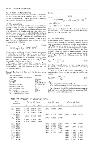
manufacturers. Table 13.4 presents R values for Otis Eq. (13.44) also reduces to Eq. (13.57) at zero casing
Spreadmaster Valves. pressure and 60 8F.
To set P d at 60 8F to a value representing P d at
Example Problem 13.6 Size port for the data given valve depth condition, real gas law must be used for cor-
below: rection:
Upstream pressure: 900 psia
Downstream pressure for subsonic P d at 60 F ¼ 520z 60 F P d , (13:58)
flow: 600 psia T d z d
Tubing ID: 2.259 in.
Gas rate: 2,500 Mscf/day where
Gas-specific gravity: 0.75 (1 for air) T d ¼ temperature at valve depth, 8R
Gas-specific heat ratio: 1.3 z d ¼ gas compressibility factor at valve depth condition.
Upstream temperature: 110 8F The z factors in Eq. (13.58) can be determined using the
Gas viscosity: 0.02 cp Hall–Yarborogh correlation. Computer spreadsheet Hall-
Choke discharge coefficient: 0.6 Yarborogh-z.xls is for this purpose.
Use Otis Spreadmaster Valve
Table 13.4 R Values for Otis Spreadmaster Valves
Port 9 ⁄ 16 -in. OD Valves 1-in. OD Valves 1 ⁄ 2 -in. OD Valves
1
Diameter (in.)
R 1 R T.E.F. R 1 R T.E.F. R 1 R T.E.F.
1
( ⁄ 8 ) 0.1250 0.1016 0.8984 0.1130 0.0383 0.9617 0.0398
0.1520 0.1508 0.8429 0.1775
0.1730 0.1958 0.8042 0.2434
3
( ⁄ 16 ) 0.1875 0.0863 0.9137 0.0945 0.0359 0.9641 0.0372
0.1960 0.2508 0.7492 0.3347
13
( ⁄ 64 ) 0.2031 0.1013 0.8987 0.1127
0.2130 0.2966 0.7034 0.4216
0.2460 0.3958 0.6042 0.6550
1
( ⁄ 4 ) 0.2500 0.1534 0.8466 0.1812 0.0638 0.9362 0.0681
9
( ⁄ 32 ) 0.2812 0.1942 0.8058 0.2410
5
( ⁄ 16 ) 0.3125 0.2397 0.7603 0.3153 0.0996 0.9004 0.1106
1
(1 ⁄ 32 ) 0.3437 0.2900 0.7100 0.4085
3
( ⁄ 8 ) 0.3750 0.3450 0.6550 0.5267 0.1434 0.8566 0.1674
7
( ⁄ 16 ) 0.4375 0.4697 0.5303 0.8857 0.1952 0.8048 0.2425
1
( ⁄ 2 ) 0.5000 0.2562 0.7438 0.3444
9
( ⁄ 16 ) 0.5625 0.3227 0.6773 0.4765
5
( ⁄ 8 ) 0.6250 0.3984 0.6016 0.6622
3
( ⁄ 4 ) 0.7500 0.5738 0.4262 1.3463