
Page 206 - Petroleum Production Engineering, A Computer-Assisted Approach
P. 206
Guo, Boyun / Computer Assited Petroleum Production Engg 0750682701_chap13 Final Proof page 202 3.1.2007 9:07pm Compositor Name: SJoearun
13/202 ARTIFICIAL LIFT METHODS
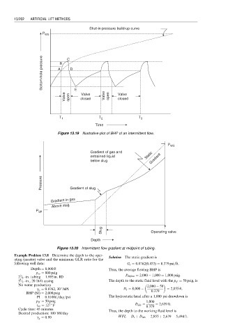
Shut-in pressure build-up curve
P WS
Bottom-hole pressure A B C D
Valve open E closed Valve open Valve
Valve
closed
T 1 T 2 T 3
Time
Figure 13.19 Illustrative plot of BHP of an intermittent flow.
P WS
Gradient of gas and
entrained liquid Static Gradient
below slug
Pressure Gradient of slug
Gradient in gas
Above slug
P SP
Slug Operating valve
Depth
Figure 13.20 Intermittent flow gradient at midpoint of tubing.
Example Problem 13.8 Determine the depth to the oper- Solution The static gradient is
ating (master) valve and the minimum GLR ratio for the
following well data: G s ¼ 0:8762(0:433) ¼ 0:379 psi=ft:
Depth ¼ 8,000 ft Thus, the average flowing BHP is
p so ¼ 800 psig
3
2 ⁄ 8 -in. tubing ¼ 1:995 in: ID P bhfave ¼ 2,000 1,000 ¼ 1,000 psig:
1
5 ⁄ 2 -in., 20 lb/ft casing The depth to the static fluid level with the p tf ¼ 50 psig, is
No water production 2,000 50
g o ¼ 0:8762, 30 8API D s ¼ 8,000 0:379 ¼ 2,855 ft:
BHP (SI) ¼ 2,000 psig
PI ¼ 0:10 bbl=day=psi The hydrostatic head after a 1,000 psi drawdown is
p tf ¼ 50 psig 1,000
t av ¼ 127 F D dds ¼ ¼ 2,639 ft:
0:379
Cycle time: 45 minutes Thus, the depth to the working fluid level is
Desired production: 100 bbl/day
g g ¼ 0:80 WFL ¼ D s þ D dds ¼ 2,855 þ 2,639 ¼ 5,494 ft: