
Page 208 - Petroleum Production Engineering, A Computer-Assisted Approach
P. 208
Guo, Boyun / Computer Assited Petroleum Production Engg 0750682701_chap13 Final Proof page 204 3.1.2007 9:07pm Compositor Name: SJoearun
13/204 ARTIFICIAL LIFT METHODS
Production Out Production Out Production Out
Gas In Gas In Gas In
Continuous Flow Intermitting Lift
Applications Applications
Open Semi-Closed Closed
a b c
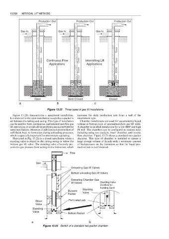
Figure 13.22 Three types of gas lift installations.
Figure 13.22b demonstrates a semiclosed installation. increases the daily production rate from a well of the
It is identical to the open installation except that a packer is intermittent type.
set between the tubing and casing. This type of installation Chamber installations are used for accumulating liquid
can be used for both continuous- and intermittent-flow gas volume at bottom hole of intermittent-flow gas lift wells.
lift operations. It avoids all the problems associated with the A chamber is an ideal installation for a low BHP and high
open installations. However, it still does not prevent flow of PI well. The chambers can be configured in various ways
well fluids back to formation during unloading processes, including using two packers, insert chamber, and reverse
which is especially important for intermittent operating. flow chamber. Figure 13.23 shows a standard two-packer
Illustrated in Fig. 13.22c is a closed installation where a chamber. This type of chamber is installed to ensure a
standing valve is placed in the tubing string or below the large storage volume of liquids with a minimum amount
bottom gas lift valve. The standing valve effectively pre- of backpressure on the formation so that the liquid pro-
vents the gas pressure from acting on the formation, which duction rate is not hindered.
Flow
Gas
Unloading Gas lift Valves
Bottom unloading Gas lift Valves
Operating Chamber Gas
lift Valves Standing Valve
modified for
handing Sand
Standing
By-pass
Valve
Packer
Bleed Perforated sub
Valve
Standing
Valve
Bottom Packer
a b
Figure 13.23 Sketch of a standard two-packer chamber.