
Page 212 - Petroleum Production Engineering, A Computer-Assisted Approach
P. 212
Guo, Boyun / Computer Assited Petroleum Production Engg 0750682701_chap14 Final Proof page 208 3.1.2007 9:10pm Compositor Name: SJoearun
14/208 ARTIFICIAL LIFT METHODS
14.1 Introduction a. Subsurface components
In addition to beam pumping and gas lift systems, other - Pump
artificial lift systems are used in the oil industry. They are - Motor
electrical submersible pumping, hydraulic piston pumping, - Seal electric cable
hydraulic jet pumping, progressive cavity pumping, and - Gas separator
plunger lift systems. All these systems are continuous
pumping systems except the plunger lift, which is very b. Surface components
similar to intermittent gas lift systems.
- Motor controller (or variable speed controller)
- Transformer
- Surface electric cable
14.2 Electrical Submersible Pump
The overall ESP system operates like any electric pump
Electrical submersible pumps (ESPs) are easy to install commonly used in other industrial applications. In ESP
and operate. They can lift extremely high volumes operations, electric energy is transported to the down-hole
from highly productive oil reservoirs. Crooked/deviated electric motor via the electric cables. These electric cables
holes present no problem. ESPs are applicable to offshore are run on the side of (and are attached to) the production
operations. Lifting costs for high volumes are generally tubing. The electric cable provides the electrical energy
very low. Limitations to ESP applications include high- needed to actuate the down-hole electric motor. The elec-
voltage electricity availability, not applicable to multiple tric motor drives the pump and the pump imparts energy
completions, not suitable to deep and high-temperature to the fluid in the form of hydraulic power, which lifts the
oil reservoirs, gas and solids production is troublesome, fluid to the surface.
and costly to install and repair. ESP systems have higher
horsepower, operate in hotter applications, are used in
dual installations and as spare down-hole units, and 14.2.1 Principle
include down-hole oil/water separation. Sand and gas ESPs are pumps made of dynamic pump stages or centri-
problems have led to new products. Automation of the fugal pump stages. Figure 14.2 gives the internal schematic
systems includes monitoring, analysis, and control. of a single-stage centrifugal pump. Figure 14.3 shows a
The ESP is a relatively efficient artificial lift. Under cutaway of a multistage centrifugal pump.
certain conditions, it is even more efficient than sucker The electric motor connects directly to the centrifugal
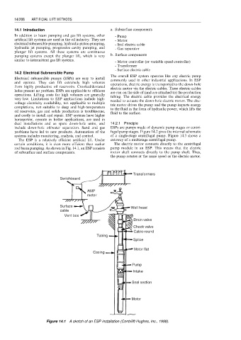
rod beam pumping. As shown in Fig. 14.1, an ESP consists pump module in an ESP. This means that the electric
of subsurface and surface components. motor shaft connects directly to the pump shaft. Thus,
the pump rotates at the same speed as the electric motor.
Transformers
Switchboard
AMP
meter
Surface Well head
cable
Vent box
Drain valve
Check valve
Cable-round
Tubing
Splice
Motor flat
Casing
Pump
Intake
Seal section
Motor
Figure 14.1 A sketch of an ESP installation (Centrilift-Hughes, Inc., 1998).