
Page 215 - Petroleum Production Engineering, A Computer-Assisted Approach
P. 215
Guo, Boyun / Computer Assited Petroleum Production Engg 0750682701_chap14 Final Proof page 211 3.1.2007 9:10pm Compositor Name: SJoearun
OTHER ARTIFICIAL LIFT METHODS 14/211
p suction ¼ 2,823 0:433(0:865)(10,000 9,800) As shown in Fig. 14.5, a hydraulic piston pump (HPP)
¼ 2,748 psia: consists of an engine with a reciprocating piston driven by
a power fluid connected by a short shaft to a piston in the
4. Computer spreadsheet HagedornBrownCorrelation.xls pump end. HPPs are usually double-acting, that is, fluid is
gives the required pump discharge pressure of being displaced from the pump on both the upstroke and
3,728 psia. the downstroke. The power fluid is injected down a tubing
5. The required pump pressure differential is string from the surface and is either returned to the surface
through another tubing (closed power fluid) or commin-
Dp ¼ p discharge p suction ¼ 3,728 2,748 ¼ 980 psi: gled with the produced fluid in the production string (open
power fluid). Because the pump and engine pistons are
The required pumping head is directly connected, the volumetric flow rates in the pump
Dp 980 and engine are related through a simple equation (Cholet,
h ¼ ¼ ¼ 2,263 feet of freshwater:
0:433 0:433 2000):
A pump
6. At throughput 10,000 bbl/day, Fig. 14.4 gives a pump- q pump ¼ q eng , (14:3)
ing head of 6,000 ft for the 100-stage pump, which A eng
yields 60 ft pumping head per stage. The required num- where
ber of stages is (2,263)=(60) ¼ 38 stages. q pump =flowrateoftheproducedfluidinthepump,bbl/day
7. At throughput 10,000 bbl/day, Fig. 14.4 gives the q eng ¼ flow rate of the power fluid, bbl/day
power of the 100-stage pump of 600 hp, which yields A pump ¼ net cross-sectional area of pump piston, in: 2
2
6 hp/stage. The required power for a 38-stage pump is A eng ¼ net cross-sectional area of engine piston, in: .
then (6)(38) ¼ 226 hp.
Equation (14.3) implies that liquid production rate is
The solution given by the computer spreadsheet ESP- proportional to the power fluid injection rate. The propor-
design.xls is shown in Table 14.1. tionality factor A pump =A eng is called the ‘‘P/E ratio.’’ By
adjusting the power fluid injection rate, the liquid produc-
tion rate can be proportionally changed. Although the P/E
14.3 Hydraulic Piston Pumping ratio magnifies production rate, a larger P/E ratio means
higher injection pressure of the power fluid.
Hydraulic piston pumping systems can lift large volumes The following pressure relation can be derived from
of liquid from great depth by pumping wells down to fairly force balance in the HPP:
low pressures. Crooked holes present minimal problems.
Both natural gas and electricity can be used as the power p eng,i p eng,d ¼ p pump,d p pump,i Þ P=Eð Þ þ F pump , (14:4)
source. They are also applicable to multiple completions where
and offshore operations. Their major disadvantages in- p eng,i ¼ pressure at engine inlet, psia
clude power oil systems being fire hazards and costly, p eng,d ¼ engine discharge pressure, psia
power water treatment problems, and high solids produc- p pump,d ¼ pump discharge pressure, psia
tion being troublesome.
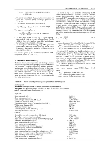
Table 14.1 Result Given by the Computer Spreadsheet ESPdesign.xls
ESPdesign.xls
Description: This spreadsheet calculates parameters for ESP selection.
Instruction: (1) Update parameter values in the Input data and Solution sections;
and (2) view result in the Solution section.
Input data
Reservoir depth (D): 10,000 ft
Reservoir pressure (p bar ): 4,350 psia
AOF in Vogel equation for IPR (q max ): 15,000 stb/day
Production fluid gravity (g L ): 0.865 1 for H 2 O
Formation volume factor of production liquid (B L ): 1.25 rb/stb
Tubing inner diameter (d ti ): 2.992 in.
Well head pressure (p wh ): 100 psia
Required pump suction pressure (p suction ): 200 psia
Desired production rate (q Ld ): 8,000 stb/day
Solution
Desired bottom-hole pressure from IPR (p wfd ) ¼ 2,823 psia
Desired production rate at pump (q Ld ) ¼ 10,000 bbl/day
Input here the minimum capacity of selected pump (q Lp ): 10,000 bbl/day
Minimum pump setting depth (D pump ) ¼ 2,997 ft
Input pump setting depth (D pump ): 9,800 ft
Pump suction pressure (p suction ) ¼ 2,748 psia
Input pump discharge pressure (p discharge ): 3,728 psia
Required pump pressure differential (Dp) ¼ 980 psia
Required pumping head (h) ¼ 2,263 ft H 2 O
Input pumping head per stage of the selected pump (h s ): 60.00 ft/stage
Input horse power per stage of the selected pump (hp s ): 6.00 hp/stage
Input efficiency of the selected pump (E p ): 0.72
Required number of stages (N s ) ¼ 38
Total motor power requirement (hp motor ) ¼ 226.35 hp