
Page 214 - Petroleum Production Engineering, A Computer-Assisted Approach
P. 214
Guo, Boyun / Computer Assited Petroleum Production Engg 0750682701_chap14 Final Proof page 210 3.1.2007 9:10pm Compositor Name: SJoearun
14/210 ARTIFICIAL LIFT METHODS
clearance around the outside of the pump down-hole 7. Determine the total power required for the pump by
equipment to allow the free flow of oil/water to the multiplying the power per stage by the number of
pump intake. The desired flow rate and tubing size will stages.
determine the total dynamic head (TDH) requirements for
the ESP system. The ‘‘TDH’’ is defined as the pressure
head immediately above the pump (in the tubing). This is Example Problem 14.1 A 10,000-ft-deep well produces
converted to feet of head (or meters of head). This TDH is 32 8API oil with GOR 50 scf/stb and zero water cut
usually given in water equivalent. Thus, TDH ¼ static through a 3-in. (2.992-in. ID) tubing in a 7-in. casing.
column of fluid (net) head + friction loss head + back- The oil has a formation volume factor of 1.25 and
pressure head. average viscosity of 5 cp. Gas-specific gravity is 0.7. The
The following procedure can be used for selecting an surface and bottom-hole temperatures are 70 8F and
ESP: 170 8F, respectively. The IPR of the well can be
described by the Vogel model with a reservoir pressure
1. Starting from well inflow performance relationship 4,350 psia and AOF 15,000 stb/day. If the well is to be
(IPR), determine a desirable liquid production rate put in production with an ESP to produce liquid at
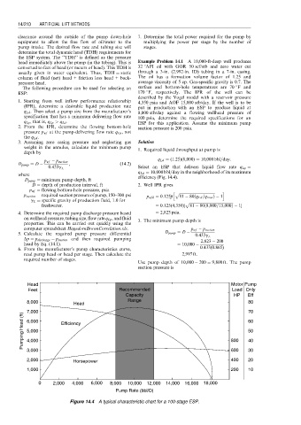
q Ld . Then select a pump size from the manufacturer’s 8,000 stb/day against a flowing wellhead pressure of
specification that has a minimum delivering flow rate 100 psia, determine the required specifications for an
q Lp , that is, q Lp > q Ld . ESP for this application. Assume the minimum pump
2. From the IPR, determine the flowing bottom-hole suction pressure is 200 psia.
pressure p wf at the pump-delivering flow rate q Lp , not
the q Ld .
3. Assuming zero casing pressure and neglecting gas Solution
weight in the annulus, calculate the minimum pump 1. Required liquid throughput at pump is
depth by
q Ld ¼ (1:25)(8,000) ¼ 10,000 bbl=day:
p wf p suction
D pump ¼ D , (14:2)
0:433g L Select an ESP that delivers liquid flow rate q Lp ¼
q Ld ¼ 10,000 bbl=day in the neighborhood of its maximum
where efficiency (Fig. 14.4).
D pump ¼ minimum pump depth, ft
D ¼ depth of production interval, ft 2. Well IPR gives
p wf ¼ flowing bottom-hole pressure, psia h p ffiffiffiffiffiffiffiffiffiffiffiffiffiffiffiffiffiffiffiffiffiffiffiffiffiffiffiffiffiffiffiffiffiffiffiffiffiffi i
p suction ¼ required suctionpressureofpump,150–300 psi p wfd ¼ 0:125p 81 80 q Ld =q max Þ 1
ð
g L ¼ specific gravity of production fluid, 1.0 for p ffiffiffiffiffiffiffiffiffiffiffiffiffiffiffiffiffiffiffiffiffiffiffiffiffiffiffiffiffiffiffiffiffiffiffiffiffiffiffiffiffiffiffiffiffiffi
freshwater. ¼ 0:125(4,350)½ 81 80 8,000=15,000Þ 1
ð
4. Determine the required pump discharge pressure based ¼ 2,823 psia:
on wellhead pressure, tubing size, flow rate q Lp , and fluid 3. The minimum pump depth is
properties. This can be carried out quickly using the
computer spreadsheet HagedornBrownCorrelation.xls. p wf p suction
5. Calculate the required pump pressure differential D pump ¼ D
0:433g L
Dp ¼ p discharge p suction and then required pumping 2,823 200
head by Eq. (14.1). ¼ 10,000
6. From the manufacturer’s pump characteristics curve, 0:433(0:865)
read pump head or head per stage. Then calculate the ¼ 2,997 ft:
required number of stages.
Use pump depth of 10,000 200 ¼ 9,800 ft. The pump
suction pressure is
Head Motor Pump
Feet Recommended Load Only
Capacity HP Eff
8,000 Head Range 80
7,000 70
Pumping Head (ft) 6,000 Efficiency 800 60
5,000
50
4,000
40
3,000 600 30
2,000 Horsepower 400 20
1,000 200 10
0 2,000 4,000 6,000 8,000 10,000 12,000 14,000 16,000 18,000
Pump Rate (bbl/D)
Figure 14.4 A typical characteristic chart for a 100-stage ESP.