
Page 216 - Petroleum Production Engineering, A Computer-Assisted Approach
P. 216
Guo, Boyun / Computer Assited Petroleum Production Engg 0750682701_chap14 Final Proof page 212 3.1.2007 9:10pm Compositor Name: SJoearun
14/212 ARTIFICIAL LIFT METHODS
Down stroke Up stroke where
p s ¼ surface operating pressure, psia
p h ¼ hydrostatic pressure of the power fluid at pump
depth, psia
p f ¼ frictional pressure loss in the power fluid injection
tubing, psi.
The required input power can be estimated from the
following equation:
Engine
5 (14:8)
Piston HP ¼ 1:7 10 q eng p s
Selection of HPP is based on the net lift defined by
p pump,i
L N ¼ D p (14:9)
G b
Pump and empirical value of P/E defined by
Piston
10,000
P=E ¼ : (14:10)
L N
The following procedure is used for selecting an HPP:
1. Starting from well IPR, determine a desirable liquid
production rate q Ld . Then calculate pump intake pres-
sure with Eq. (14.6).
2. Calculate net lift with Eq. (14.9) and P/E ratio with
Eq. (14.10).
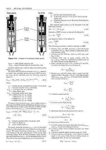
Figure 14.5 A sketch of a hydraulic piston pump. 3. Calculate flow rate at pump suction point by
q Ls ¼ B o q Ld , where B o is formation volume factor of
oil. Then estimate pump efficiency E p .
p pump,i ¼ pump intake pressure, psia 4. Select a pump rate ratio N=N max between 0.2 and 0.8.
F pump ¼ pump friction-induced pressure loss, psia. Calculate the design flow rate of pump by
Equation (14.4) is also valid for open power fluid system q Ls
where p eng,d ¼ p pump,d . q pd ¼ E p N=N max Þ :
ð
The pump friction-induced pressure loss F pump depends
on pump type, pumping speed, and power fluid viscosity. 5. Based on q pd and P/E values, select a pump from the
Its value can be estimated with the following empirical manufacturer’s literature and get rated displacement
equation: values q pump , q eng , and N max . If not provided, calculate
N=N max flow rates per stroke by
7:1e Bq total , (14:5)
F pump ¼ 50g L 0:99 þ 0:01n pf
where q 0 pump ¼ q pump
N max
g L ¼ specific gravity of production liquid, 1.0 for H 2 O and
n pf ¼ viscosity of power fluid, centistokes
q total ¼ total liquid flow rate, bbl/day q 0 eng ¼ q eng :
N ¼ pump speed, spm N max
N max ¼ maximum pump speed, spm
3
B ¼ 0:000514 for 2 ⁄ 8 -in. tubing 6. Calculate pump speed by
7
¼ 0:000278 for 2 ⁄ 8 -in. tubing N
1
¼ 0:000167 for 3 ⁄ 2 -in. tubing N ¼ N max :
1
¼ 0:000078 for 4 ⁄ 2 -in. tubing. N max
The pump intake pressure p pump,i can be determined on 7. Calculate power fluid rate by
the basis of well IPR and desired liquid production rate q Ld . N
If the IPR follows Vogel’s model, then for an HPP installed q pf ¼ q eng :
close to bottom hole, p pump,i can be estimated using N max E eng
h p ffiffiffiffiffiffiffiffiffiffiffiffiffiffiffiffiffiffiffiffiffiffiffiffiffiffiffiffiffiffiffiffiffiffiffiffiffiffi i
ð
p pump,i ¼ 0:125 p p 81 80 q Ld =q max Þ 1 G b 8. Determine the return production flow rate by
D D p , (14:6) q total ¼ q pf þ q Ls
for open power fluid system or
where
q total ¼ q Ls
G b ¼ pressure gradient below the pump, psi/ft
D ¼ reservoir depth, ft for closed power fluid system.
D p ¼ pump setting depth, ft.
9. Calculate pump and engine discharge pressure p pump,d
The pump discharge pressure p pump;d can be calculated and p eng,d based on tubing performance.
based on wellhead pressure and production tubing perfor- 10. Calculate pump friction-induced pressure loss using
mance. The engine discharge pressure p eng;d can be calcu- Eq. (14.5).
lated based on the flow performance of the power fluid 11. Calculate required engine pressure using Eq. (14.4).
returning tubing. With all these parameter values known, 12. Calculate pressure change Dp inj from surface to engine
theengineinletpressurep eng,i canbecalculatedbyEq.(14.6). depth in the power fluid injection tubing based on
Then the surface operating pressure can be estimated by single-phase flow. It has two components:
p s ¼ p eng,i p h þ p f , (14:7) Dp inj ¼ p potential p friction