
Page 221 - Petroleum Production Engineering, A Computer-Assisted Approach
P. 221
Guo, Boyun / Computer Assited Petroleum Production Engg 0750682701_chap14 Final Proof page 217 3.1.2007 9:10pm Compositor Name: SJoearun
OTHER ARTIFICIAL LIFT METHODS 14/217
Electronic Controller/
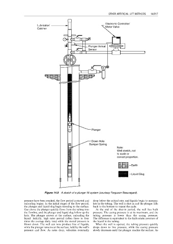
Lubricator/ Motor Valve
Catcher
Plunger Arrival
Sensor
Plunger
Down Hole
Bumper Spring
Note:
Well sketch, not
to scale or
correct proportion.
Earth
Liquid Slug
Figure 14.9 A sketch of a plunger lift system (courtesy Ferguson Beauregard).
pressure have been reached, the flow period is started and drop below the critical rate, and liquids begin to accumu-
unloading begins. In the initial stages of the flow period, late in the tubing. The well is shut in and the plunger falls
the plunger and liquid slug begin traveling to the surface. back to the bottom to repeat the cycle.
Gas above the plunger quickly flows from the tubing into At the end of the shut-in period, the well has built
the flowline, and the plunger and liquid slug follow up the pressure. The casing pressure is at its maximum, and the
hole. The plunger arrives at the surface, unloading the tubing pressure is lower than the casing pressure.
liquid. Initially, high rates prevail (often three to four The difference is equivalent to the hydrostatic pressure of
times the average daily rate) while the stored pressure is the liquid in the tubing.
blown down. The well can now produce free of liquids, When the well is opened, the tubing pressure quickly
while the plunger remains at the surface, held by the well’s drops down to line pressure, while the casing pressure
pressure and flow. As rates drop, velocities eventually slowly decreases until the plunger reaches the surface. As