
Page 224 - Petroleum Production Engineering, A Computer-Assisted Approach
P. 224
Guo, Boyun / Computer Assited Petroleum Production Engg 0750682701_chap14 Final Proof page 220 3.1.2007 9:10pm Compositor Name: SJoearun
14/220 ARTIFICIAL LIFT METHODS
1440 p sh 120
N C max ¼ , (14:29) p c ¼ p L max þ ¼ 100 þ ¼ 300 to 340 psi:
D þ D V slug L þ V slug L f sl 0:5to0:6
V r V fg V fl
Since the well has 800 psi of available casing pressure, it
where
N C max ¼ the maximum number of cycles per day meets the pressure requirements for plunger lift.
V fg ¼ plunger falling velocity in gas, ft/min The Foss and Gaul–type method can be used to deter-
V fl ¼ plunger falling velocity in liquid, ft/min mine plunger lift operating range. Basic parameters are
V r ¼ plunger rising velocity, ft/min. given in Table 14.3.
Since the Foss and Gaul–type calculations involve de-
The maximum liquid production rate can be expressed as termination of Z-factor values in Eq. (14.28) at different
q L max ¼ N C max V slug : (14:30) pressures, a spreadsheet program PlungerLift.xls was
developed to speed up the calculation procedure. The
The required GLR can be expressed as solution is given in Table 14.4.
It was given that the estimated production when
V g
GLR min ¼ : (14:31) unloaded is 200 Mcfd with 10 bbl/day of liquid
V slug
(GLR ¼ 200=10 ¼ 20 Mscf=bbl), and the maximum casing
pressure buildup is 800 psi. From the Table 14.4, find
Example Problem 14.3: Plunger Lift Calculations casing pressure of about 800 psi, GLR of 20 Mscf/bbl,
Calculate required GLR, casing pressure, and plunger lift and production rates of 10 bbl/day. This occurs at slug
operating range for the following given well data: sizes between about 0.25 and 3 bbl. The well will operate
on plunger lift.
Gas rate: 200 Mcfd expected
when unloaded
Liquid rate: 10 bbl/day expected 14.6 Hydraulic Jet Pumping
when unloaded
Liquid gradient: 0.45 psi/ft Figure 14.10 shows a hydraulic jet pump installation. The
Tubing, ID: 1.995 in. pump converts the energy from the injected power fluid
Tubing, OD: 2.375 in. (water or oil) to pressure that lifts production fluids.
Casing, ID: 4.56 in. Because there is no moving parts involved, dirty and
Depth to plunger: 7,000 ft gassy fluids present no problem to the pump. The jet
Line pressure: 100 psi pumps can be set at any depth as long as the suction
Available casing pressure: 800 psi pressure is sufficient to prevent pump cavitation problem.
Reservoir pressure: 1200 psi The disadvantage of hydraulic jet pumps is their low
Average Z factor: 0.99 efficiency (20–30%).
Average temperature: 140 8F
Plunger weight: 10 lb
14.6.1 Working Principle
Plunger fall in gas: 750 fpm Figure 14.11 illustrates the working principle of a
Plunger fall in liquid: 150 fpm hydraulic jet pump. It is a dynamic-displacement pump
Plunger rise velocity: 1,000 fpm
that differs from a hydraulic piston pump in the manner in
which it increases the pressure of the pumped fluid with a
Solution The minimum required GLR bya rule of thumb is jet nozzle. The power fluid enters the top of the pump from
an injection tubing. The power fluid is then accelerated
D 7,000
GLR min ¼ 400 ¼ 400 ¼ 2,800 scf=bbl: through the nozzle and mixed with the produced fluid in
1,000 1,000 the throat of the pump. As the fluids mix, the momentum
The well’s GLR of 2,857 scf/bbl is above 2,800 scf/bbl and of the power fluid is partially transferred to the produced
is, therefore, considered adequate for plunger lift. fluid and increases its kinetic energy (velocity head).
The minimum required casing pressure can be estimated
using two rules of thumb. The simple rule of thumb gives
p c ¼ 1:5p L max ¼ (1:5)(100) ¼ 150 psi: Table 14.3 Summary of Calculated Parameters
To calculate the minimum required casing pressure with Tubing inner cross-sectional area (A t ) ¼ 3:12 in: 2
the improved rule of thumb, the slug hydrostatic pressure Annulus cross-sectional area (A a ) ¼ 11:90 in: 2
needs to be known. For this case, assuming 10 cycles/day, Plunger-weight pressure (P p ) ¼ 3.20 psi
equivalent to a plunger trip every 2.4 hours, and 10 bbls of Slippage factor (F gs ) ¼ 1.14
liquid, the plunger will lift 1 bbl/cycle. The hydrostatic Tubing inner capacity (L) ¼ 258.80 ft/bbl
3
pressure of 1 bbl of liquid in 2 ⁄ 8 -in. tubing with a The average temperature (T avg ) ¼ 600 8R
0.45-psi/ft liquid gradient is about 120 psi. Then
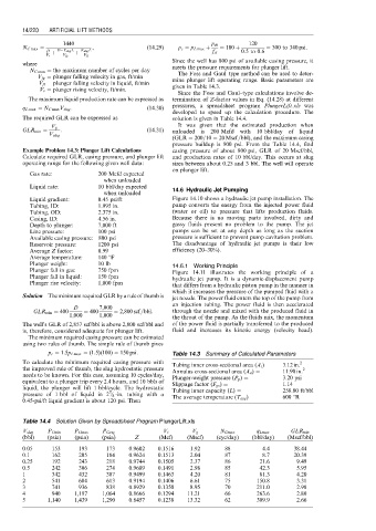
Table 14.4 Solution Given by Spreadsheet Program PlungerLift.xls
V slug P Cmin P Cmax P Cavg V t V g N Cmax q Lmax GLR min
(bbl) (psia) (psia) (psia) Z (Mcf) (Mscf) (cyc/day) (bbl/day) (Mscf/bbl)
0.05 153 193 173 0.9602 0.1516 1.92 88 4.4 38.44
0.1 162 205 184 0.9624 0.1513 2.04 87 8.7 20.39
0.25 192 243 218 0.9744 0.1505 2.37 86 21.6 9.49
0.5 242 306 274 0.9689 0.1491 2.98 85 42.3 5.95
1 342 432 387 0.9499 0.1463 4.20 81 81.3 4.20
2 541 684 613 0.9194 0.1406 6.61 75 150.8 3.31
3 741 936 838 0.8929 0.1350 8.95 70 211.0 2.98
4 940 1,187 1,064 0.8666 0.1294 11.21 66 263.6 2.80
5 1,140 1,439 1,290 0.8457 0.1238 13.32 62 309.9 2.66