Page 225 - Petroleum Production Engineering, A Computer-Assisted Approach
P. 225

Guo, Boyun / Computer Assited Petroleum Production Engg 0750682701_chap14 Final Proof page 221  3.1.2007 9:10pm Compositor Name: SJoearun


                                                                           OTHER ARTIFICIAL LIFT METHODS  14/221
                                               Power               p 2 ¼ discharge pressure, psia
                                               fluid               q 2 ¼ q 1 þ q 3 , total fluid rate in return column, bbl/day
                                                                   p 3 ¼ intake pressure, psia
                                               Pump                q 3 ¼ intake (produced) fluid rate, bbl/day
                                               tubing              A j ¼ jet nozzle area, in. 2
                                                                   A s ¼ net throat area, in. 2
                                               Casing
                                                                                     2
                                                                   A t ¼ total throat area, in. .
                                               Nozzle
                                                                   The following dimensionless variables are also used in
                                               Production        jet pump literature (Cholet, 2000):
                                               inlet chamber
                                               Throat               A j
                                                                 R ¼                                (14:32)
                                               Diffuser             A t
                                                                     q 3
                                                                 M ¼                                (14:33)
                                                                     q 1
                                                                     p 2   p 3
                                                                 H ¼                                (14:34)
                                                                     p 1   p 2
                                                                 h ¼ MH,                            (14:35)
                                               Combined
                                               fluid return      where
                                                                    R ¼ dimensionless nozzle area
                                                                   M ¼ dimensionless flow rate
                                                                   H ¼ dimensionless head
                                                                    h ¼ pump efficiency.
                                               Well
                                               production
                                                                 14.6.3 Selection of Jet Pumps
                                                                 Selection of jet pumps is made on the basis of manufacturer’s
                                                                 literatures where pump performance charts are usually avail-
                                                                 able. Figure 14.12 presents an example chart. It shows the
                       Figure 14.10 Sketch of a hydraulic jet pump installation.  effect of M on H and h. For a given jet pump specified by R
                                                                 value, there exists a peak efficiency h p . It is good field practice
                       Some of the kinetic energy of the mixed stream is con-
                       verted to static pressure head in a carefully shaped diffuser  to attempt to operate the pump at its peak efficiency. If M p
                       section of expanding area. If the static pressure head is  and H p are used to denote M and H at the peak efficiency,
                       greater than the static column head in the annulus, the  respectively, pump parameters should be designed using
                       fluid mixture in the annulus is lifted to the surface.  q 3
                                                                 M p ¼                              (14:36)
                                                                     q 1
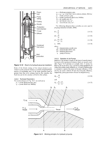
                       14.6.2 Technical Parameters               and
                       The nomenclatures in Fig. 14.11 are defined as
                                                                     p 2   p 3
                         p 1 ¼ power fluid pressure, psia        H p ¼    ,                         (14:37)
                         q 1 ¼ power fluid rate, bbl/day             p 1   p 2
                                                             A j  A s        A t


                                 P  q 3
                                  3


                                P  q 1                                                P  q 2
                                                                                       2
                                 1
                                Nozzle                             Throat             Diffuser


                                                      A                    B
                                            Figure 14.11 Working principle of a hydraulic jet pump.
   220   221   222   223   224   225   226   227   228   229   230