
Page 220 - Petroleum Production Engineering, A Computer-Assisted Approach
P. 220
Guo, Boyun / Computer Assited Petroleum Production Engg 0750682701_chap14 Final Proof page 216 3.1.2007 9:10pm Compositor Name: SJoearun
14/216 ARTIFICIAL LIFT METHODS
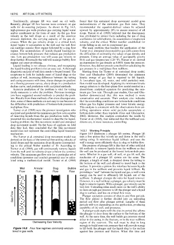
Traditionally, plunger lift was used on oil wells. found that this entrained drop movement model gives
Recently, plunger lift has become more common on gas underestimates of the minimum gas flow rates. They
wells for de-watering purposes. As shown in Fig. 14.8, recommended the equation-derived values be adjusted
high-pressure gas wells produce gas carrying liquid water upward by approximately 20% to ensure removal of all
and/or condensate in the form of mist. As the gas flow drops. Turner et al. (1969) believed that the discrepancy
velocity in the well drops as a result of the reservoir was attributed to several facts including the use of drag
pressure depletion, the carrying capacity of the gas de- coefficients for solid spheres, the assumption of stagnation
creases. When the gas velocity drops to a critical level, velocity, and the critical Weber number established for
liquid begins to accumulate in the well and the well flow drops falling in air, not in compressed gas.
can undergo annular flow regime followed by a slug flow The main problem that hinders the application of the
regime. The accumulation of liquids (liquid loading) in- Turner et al. entrained drop model to gas wells comes from
creases bottom-hole pressure that reduces gas production the difficulties of estimating the values of gas density and
rate. Low gas production rate will cause gas velocity to pressure. Using an average value of gas-specific gravity
drop further. Eventually the well will undergo bubbly flow (0.6) and gas temperature (120 8F), Turner et al. derived
regime and cease producing. an expression for gas density as 0.0031 times the pressure.
Liquid loading is not always obvious, and recognizing However, they did not present a method for calculating the
the liquid-loading problem is not an easy task. A thorough gas pressure in a multiphase flow wellbore.
diagnostic analysis of well data needs to be performed. The Starting from the Turner et al. entrained drop model,
symptoms to look for include onset of liquid slugs at the Guo and Ghalambor (2005) determined the minimum
surface of well, increasing difference between the tubing kinetic energy of gas that is required to lift liquids.
and casing pressures with time, sharp changes in gradient A four-phase (gas, oil, water, and solid particles) mist-
on a flowing pressure survey, sharp drops in a production flow model was developed. Applying the minimum kinetic
decline curve, and prediction with analytical methods. energy criterion to the four-phase flow model resulted in a
Accurate prediction of the problem is vital for taking closed-form analytical equation for predicting the min-
timely measures to solve the problem. Previous investiga- imum gas flow rate. Through case studies, Guo and Gha-
tors have suggested several methods to predict the prob- lambor demonstrated that this new method is more
lem. Results from these methods often show discrepancies. conservative and accurate. Their analysis also indicates
Also, some of these methods are not easy to use because of that the controlling conditions are bottom-hole conditions
the difficulties with prediction of bottom-hole pressure in where gas has higher pressure and lower kinetic energy.
multiphase flow. This analysis is consistent with the observations from air-
Turner et al. (1969) were the pioneer investigators who drilling operations where solid particles accumulate at
analyzed and predicted the minimum gas flow rate capable bottom-hole rather than top-hole (Guo and Ghalambor,
of removing liquids from the gas production wells. They 2002). However, this analysis contradicts the results by
presented two mathematical models to describe the liquid- Turner et al. (1969), that indicated that the wellhead con-
loading problem: the film movement model and entrained ditions are, in most instances, controlling.
drop movement model. On the basis of analyses on field
data they had, they concluded that the film movement
model does not represent the controlling liquid transport 14.5.1 Working Principle
mechanism. Figure 14.9 illustrates a plunger lift system. Plunger lift
The Turner et al. entrained drop movement model was uses a free piston that travels up and down in the well’s
derived on the basis of the terminal-free settling velocity of tubing string. It minimizes liquid fallback and uses the
liquid drops and the maximum drop diameter correspond- well’s energy more efficiently than in slug or bubble flow.
ing to the critical Weber number of 30. According to The purpose of plunger lift is like that of other artificial
Turner et al. (1969), gas will continuously remove liquids lift methods: to remove liquids from the wellbore so that
from the well until its velocity drops to below the terminal the well can be produced at the lowest bottom-hole pres-
velocity. The minimum gas flow rate for a particular set of sures. Whether in a gas well, oil well, or gas lift well, the
conditions (pressure and conduit geometry) can be calcu- mechanics of a plunger lift system are the same. The
lated using a mathematical model. Turner et al. (1969) plunger, a length of steel, is dropped down the tubing to
the bottom of the well and allowed to travel back to the
surface. It provides a piston-like interface between liquids
Mist Annular Slug Bubble and gas in the wellbore and prevents liquid fallback. By
Flow Flow Flow Flow providing a ‘‘seal’’ between the liquid and gas, a well’s own
energy can be used to efficiently lift liquids out of the
wellbore. A plunger changes the rules for liquid removal.
However, in a well without a plunger, gas velocity must be
high to remove liquids. With a plunger, gas velocity can be
very low. Unloading relies much more on the well’s ability
to store enough gas pressure to lift the plunger and a liquid
Gas Flow The flow period is further divided into an unloading
slug to surface, and less on critical flow rates.
Plunger operation consists of shut-in and flow periods.
period and flow after plunger arrival. Lengths of these
periods will vary depending on the application, producing
capability of the well, and pressures.
A plunger cycle starts with the shut-in period that allows
the plunger to drop from the surface to the bottom of the
well. At the same time, the well builds gas pressure stored
either in the casing, in the fracture, or in the near wellbore
Decreasing Gas Velocity region of the reservoir. The well must be shut in long
enough to build reservoir pressure that will provide energy
Figure 14.8 Four flow regimes commonly encoun- to lift both the plunger and the liquid slug to the surface
tered in gas wells. against line pressure and friction. When this time and