
Page 217 - Petroleum Production Engineering, A Computer-Assisted Approach
P. 217
Guo, Boyun / Computer Assited Petroleum Production Engg 0750682701_chap14 Final Proof page 213 3.1.2007 9:10pm Compositor Name: SJoearun
OTHER ARTIFICIAL LIFT METHODS 14/213
13. Calculate required surface operating pressure by the required specifications for the HPP for this
application. Assume the overall efficiencies of the engine,
p so ¼ p eng,i Dp inj : HHP, and surface pump to be 0.90, 0.80, and 0.85,
14. Calculate required surface operating horsepower by respectively.
HP so ¼ 1:7 10 5 q pf p so , Solution This problem is solved by computer spreadsheet
E s
HydraulicPistonPump.xls, as shown in Table 14.2.
where E s is the efficiency of surface pump.
Example Problem 14.2 A 10,000-ft-deep well has a
potential to produce 40 8API oil with GOR 150 scf/stb 14.4 Progressive Cavity Pumping
and 10% water cut through a 2-in. (1.995-in. ID) tubing The progressive cavity pump (PCP) is a positive
in a 7-in. casing with a pump installation. The oil has a displacement pump, using an eccentrically rotating sin-
formation volume factor of 1.25 and average viscosity of gle-helical rotor, turning inside a stator. The rotor is
5 cp. Gas- and water-specific gravities are 0.7 and 1.05, usually constructed of a high-strength steel rod, typi-
respectively. The surface and bottom-hole temperatures cally double-chrome plated. The stator is a resilient
are 80 and 180 8F, respectively. The IPR of the well can elastomer in a double-helical configuration molded inside
be described by Vogel’s model with a reservoir pressure a steel casing. A sketch of a PCP system is shown in
2,000 psia and AOF 300 stb/day. If the well is to be put in Fig. 14.6.
production with an HPP at a depth of 9,700 ft in an open Progressive cavity pumping systems can be used for
power fluid system to produce liquid at 200 stb/day lifting heavy oils at a variable flow rate. Solids and free
against a flowing wellhead pressure of 75 psia, determine gas production present minimal problems. They can be
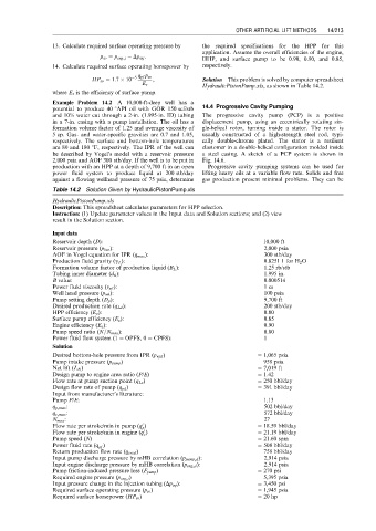
Table 14.2 Solution Given by HydraulicPistonPump.xls
HydraulicPistonPump.xls
Description: This spreadsheet calculates parameters for HPP selection.
Instruction: (1) Update parameter values in the Input data and Solution sections; and (2) view
result in the Solution section.
Input data
Reservoir depth (D): 10,000 ft
Reservoir pressure (p bar ): 2,000 psia
AOF in Vogel equation for IPR (q max ): 300 stb/day
Production fluid gravity (g L ): 0.8251 1 for H 2 O
Formation volume factor of production liquid (B L ): 1.25 rb/stb
Tubing inner diameter (d ti ): 1.995 in.
B value: 0.000514
Power fluid viscosity (v pf ): 1 cs
Well head pressure (p wh ): 100 psia
Pump setting depth (D p ): 9,700 ft
Desired production rate (q Ld ): 200 stb/day
HPP efficiency (E p ): 0.80
Surface pump efficiency (E s ): 0.85
Engine efficiency (E e ): 0.90
Pump speed ratio (N=N max ): 0.80
Power fluid flow system (1 ¼ OPFS, 0 ¼ CPFS): 1
Solution
Desired bottom-hole pressure from IPR (p wfd ) ¼ 1,065 psia
Pump intake pressure (p pump ) ¼ 958 psia
Net lift (L N ) ¼ 7,019 ft
Design pump to engine area ratio (P/E) ¼ 1.42
Flow rate at pump suction point (q Ls ) ¼ 250 bbl/day
Design flow rate of pump (q pd ) ¼ 391 bbl/day
Input from manufacturer’s literature:
Pump P/E: 1.13
q p,max : 502 bbl/day
q e,max : 572 bbl/day
N max : 27
0
Flow rate per stroke/min in pump (q ) ¼ 18.59 bbl/day
p
0
Flow rate per stroke/min in engine (q ) ¼ 21.19 bbl/day
e
Pump speed (N) ¼ 21.60 spm
Power fluid rate (q pf ) ¼ 508 bbl/day
Return production flow rate (q total ) ¼ 758 bbl/day
Input pump discharge pressure by mHB correlation (p pump,d ): 2,914 psia
Input engine discharge pressure by mHB correlation (p eng,d ): 2,914 psia
Pump friction-induced pressure loss (F pump ) ¼ 270 psi
Required engine pressure (p eng,i ) ¼ 5,395 psia
Input pressure change in the injection tubing (Dp inj ): ¼ 3,450 psi
Required surface operating pressure (p so ) ¼ 1,945 psia
Required surface horsepower (HP so ) ¼ 20 hp