
Page 219 - Petroleum Production Engineering, A Computer-Assisted Approach
P. 219
Guo, Boyun / Computer Assited Petroleum Production Engg 0750682701_chap14 Final Proof page 215 3.1.2007 9:10pm Compositor Name: SJoearun
OTHER ARTIFICIAL LIFT METHODS 14/215
D
Section
Stator Centerline
Rotor Centerline
P r
P s
E
D+2E D+4E
Pump Assembly Rotor Stator
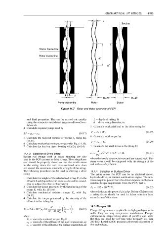
Figure 14.7 Rotor and stator geometry of PCP.
and fluid properties. This can be carried out quickly L ¼ depth of tubing, ft
using the computer spreadsheet HagedornBrownCorre- d ¼ drive string diameter, in.
lation.xls. 5. Calculate total axial load to the drive string by
4. Calculate required pump head by
F ¼ F b þ W r : (14:19)
DP ¼ p pd p pi : (14:17)
6. Calculate total torque by
5. Calculate the required number of pitches n p using Eq.
(14.14). T ¼ T m þ T v : (14:20)
6. Calculate mechanical resistant torque with Eq. (14.15).
7. Calculate the load on thrust bearing with Eq. (14.16). 7. Calculate the axial stress in the string by
4 p ffiffiffiffiffiffiffiffiffiffiffiffiffiffiffiffiffiffiffiffiffiffiffiffiffiffiffiffiffiffiffiffiffiffiffiffiffiffiffiffi
2 2
2
14.4.3 Selection of Drive String s t ¼ pd 3 F d þ 64T 144, (14:21)
Sucker rod strings used in beam pumping are also
used in the PCP systems as drive strings. The string diam- where the tensile stress s t is in pound per square inch. This
eter should be properly chosen so that the tensile stress stress value should be compared with the strength of the
in the string times the rod cross-sectional area does rod with a safety factor.
not exceed the maximum allowable strength of the string.
The following procedure can be used in selecting a drive 14.4.4 Selection of Surface Driver
string: The prime mover for PCP can be an electrical motor,
1. Calculate the weight of the selected rod string W r in the hydraulic drive, or internal-combustion engine. The min-
effluent fluid (liquid level in annulus should be consid- imum required power from the driver depends on the total
ered to adjust the effect of buoyancy). resistant torque requirement from the PCP, that is,
2. Calculate the thrust generated by the head rating of the P h ¼ 1:92 10 TN, (14:22)
4
pump F b with Eq. (14.16).
3. Calculate mechanical resistant torque T m with Eq. where the hydraulic power P h is in hp. Driver efficiency and
(14.15). a safety factor should be used in driver selection from
4. Calculate the torque generated by the viscosity of the manufacturer’s literature.
effluent in the tubing by
!
d 3 1 m s 14.5 Plunger Lift
6
T v ¼ 2:4 10 m f LN 1 , (14:18)
(D d) ln m s m f Plunger lift systems are applicable to high gas–liquid ratio
wells. They are very inexpensive installations. Plunger
m f
where automatically keeps tubing clean of paraffin and scale.
T v ¼ viscosity-resistant torque, lb f -ft But they are good for low-rate wells normally less than
m f ¼ viscosity of the effluent at the inlet temperature, cp 200 B/D. Listiak (2006) presents a thorough discussion of
m s ¼ viscosity of the effluent at the surface temperature, cp this technology.