
Page 218 - Petroleum Production Engineering, A Computer-Assisted Approach
P. 218
Guo, Boyun / Computer Assited Petroleum Production Engg 0750682701_chap14 Final Proof page 214 3.1.2007 9:10pm Compositor Name: SJoearun
14/214 ARTIFICIAL LIFT METHODS
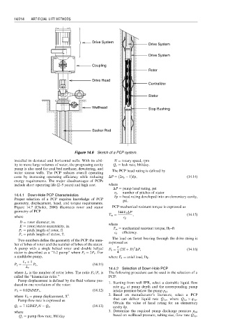
Drive System
Drive System
Drive System
Coupling
Rotor
Drive Head
Centralizer
Stator
Wellhead Stop Bushing
Sucker Rod
Figure 14.6 Sketch of a PCP system.
installed in deviated and horizontal wells. With its abil- N ¼ rotary speed, rpm
ity to move large volumes of water, the progressing cavity Q s ¼ leak rate, bbl/day.
pump is also used for coal bed methane, dewatering, and The PCP head rating is defined by
water source wells. The PCP reduces overall operating
costs by increasing operating efficiency while reducing DP ¼ 2n p 1 dp, (14:14)
energy requirements. The major disadvantages of PCPs
include short operating life (2–5 years) and high cost. where
DP ¼ pump head rating, psi
n p ¼ number of pitches of stator
14.4.1 Down-Hole PCP Characteristics dp ¼ head rating developed into an elementary cavity,
Proper selection of a PCP requires knowledge of PCP psi.
geometry, displacement, head, and torque requirements.
Figure 14.7 (Cholet, 2000) illustrates rotor and stator PCP mechanical resistant torque is expressed as
geometry of PCP 144V 0 DP
T m ¼ , (14:15)
where e p
D ¼ rotor diameter, in. where
E ¼ rotor=stator eccentricity, in.
P r ¼ pitch length of rotor, ft T m ¼ mechanical resistant torque, lb f -ft
e p ¼ efficiency.
P s ¼ pitch length of stator, ft.
The load on thrust bearing through the drive string is
Two numbers define the geometry of the PCP: the num-
ber of lobes of rotor and the number of lobes of the stator. expressed as
A pump with a single helical rotor and double helical F b ¼ ð 2E þ DÞ DP, (14:16)
2
stator is described as a ‘‘1-2 pump’’ where P s ¼ 2P r . For 4
a multilobe pump, where F b ¼ axial load, lb f .
L r þ 1
P s ¼ P r , (14:11)
14.4.2 Selection of Down-Hole PCP
L r
where L r is the number of rotor lobes. The ratio P r =P s is The following procedure can be used in the selection of a
called the ‘‘kinematics ratio.’’ PCP:
Pump displacement is defined by the fluid volume pro-
duced in one revolution of the rotor: 1. Starting from well IPR, select a desirable liquid flow
rate q Lp at pump depth and the corresponding pump
V 0 ¼ 0:028DEP s , (14:12) intake pressure below the pump p pi .
3
where V 0 ¼ pump displacement, ft . 2. Based on manufacturer’s literature, select a PCP
Pump flow rate is expressed as that can deliver liquid rate Q Lp , where Q Lp > q Lp .
Obtain the value of head rating for an elementary
Q c ¼ 7:12DEP s N Q s , (14:13) cavity dp.
where 3. Determine the required pump discharge pressure p pd
Q c ¼ pump flow rate, bbl/day based on wellhead pressure, tubing size, flow rate Q Lp ,