
Page 226 - Petroleum Production Engineering, A Computer-Assisted Approach
P. 226
Guo, Boyun / Computer Assited Petroleum Production Engg 0750682701_chap14 Final Proof page 222 3.1.2007 9:10pm Compositor Name: SJoearun
14/222 ARTIFICIAL LIFT METHODS
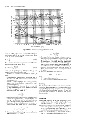
Figure 14.12 Example jet pump performance chart.
where M p and H p values can be determined from the given p 2 ¼ p 3 þ H p p 1 :
performance chart. If the H scale is not provided in the 1 þ Hp
chart, H p can be determined by 8. If the p 2 value is greater than p 2,r value with a reason-
able safety factor, the chosen pump is okay to use, and
h p
H p ¼ : (14:38) go to Step 9. Otherwise, go to Step 3 to choose a
M p
different pump. If no pump meets the requirements
The power fluid flow rate and pump pressure differential for the desired production rate q 3 and/or lifting pres-
are related through jet nozzle size by sure p 2,r , go to Step 2 to change pump setting depth or
r ffiffiffiffiffiffiffiffiffiffiffiffiffiffiffi reduce the value of the desired fluid production rate q 3 .
p 1 p 3
q 1 ¼ 1214:5A j , (14:39) 9. Calculate the required surface operating pressure p s
based on the values of p 1 and q 1 and single-phase flow
g 1
in tubing.
where g 1 is the specific gravity of the power fluid, q 1 is in
bbl/day, and p 1 and p 3 are both in psi. 10. Calculate input power requirement by
The following procedure can be taken to select a jet 5
pump: HP ¼ 1:7 10 q 1 p s ,
where
1. Select a desired production rate of reservoir fluid q 3 HP ¼ required input power, hp
based on well IPR. Determine the required bottom-
hole pressure p wf . p s ¼ required surface operating pressure, psia.
2. Design a pump setting depth D and estimate required
pump intake pressure p 3 based on p wf and flow gradi- Summary
ent below the pump.
3. From manufacturer’s literature, choose a pump with This chapter provides a brief introduction to the principles
R value and determine M p and H p values for the pump of electrical submersible pumping, hydraulic piston pump-
based on pump performance curves. ing, hydraulic jet pumping, progressive cavity pumping,
4. Calculate power fluid rate q 1 by and plunger lift systems. Design guidelines are also pre-
sented. Example calculations are illustrated with spread-
sheet programs.
q 3
q 1 ¼ :
M p
5. Based on tubing flow performance, calculate the re-
quired discharge pressure p 2,r using production rate References
q 2 ¼ q 1 þ q 3 . This step can be performed with the abercrombie, b. Plunger lift. In: The Technology of Artifi-
spreadsheet program HagedornBrownCorrelation.xls. cial Lift Methods (Brown, K.E., ed.), Vol. 2b. Tulsa:
6. Determine the power fluid pressure p 1 required to PennWell Publishing Co., 1980, pp. 483–518.
provide power fluid rate q 1 with Eq. (14.39), that is,
beeson, c.m., knox, d.g., and stoddard, j.h. Plunger lift
2 correlation equations and nomographs. Presented at
q 1 AIME Petroleum Branch Annual meeting, 2–5 Octo-
p 1 ¼ p 3 þ g 1 :
1214:5A j ber 1955, New Orleans, Louisiana. Paper 501-G.
7. Determine the available discharge pressure p 2 from the brown, k.e. The Technology of Artificial Lift Methods,
pump with Eq. (14.37), that is, Vol. 2b. Tulsa: PennWell Publishing Co., 1980.