
Page 231 - Petroleum Production Engineering, A Computer-Assisted Approach
P. 231
Guo, Boyun / Computer Assited Petroleum Production Engg 0750682701_chap15 Final Proof page 229 22.12.2006 6:14pm
WELL PROBLEM IDENTIFICATION 15/229
. Near wellbore damage/stimulation r w ¼ wellbore radius
. Rate-dependent skin S ¼ total skin factor.
. Boundary identification
. Partial penetration effect on flow Horizontal Linear Flow. For hydraulically fractured
. Effective fracture length wells, the horizontal linear flow can be mathematically
. Effective fracture conductivity described in consistent units as
. Dual-porosity characteristics (storativity and transmis- " s ffiffiffiffiffiffiffiffiffiffiffiffiffiffiffi #
sivity ratios) qBm pk y t
p wf ¼ p i þ S , (15:2)
The theoretical basis of pressure transient data analysis is 2pk y h fmc t x 2 f
beyond the scope of this book. It can be found elsewhere
(Chaudhry, 2004; Horne, 1995; Lee et al., 2003). Modern where x f is fracture half-length and k y is the permeability
computer software packages are available for data anal- in the direction perpendicular to the fracture face.
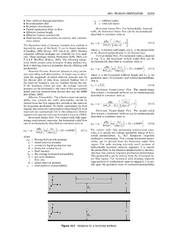
yses. These packages include PanSystem (EPS, 2004) and Vertical Radial Flow. For horizontal wells as depicted
F.A.S.T. WellTest (Fekete, 2003). The following subsec- in Fig. 15.2, the early-time vertical radial flow can be
tions briefly present some principles of data analyses that mathematically described in consistent units as
lead to deriving reservoir properties directly affecting well
productivity. p wf ¼ p i qBm ln k yz t þ 2S þ 0:80907 , (15:3)
Reservoir Pressure. Reservoir pressure is a key param- 4pk yz L fmc t r 2 w
eter controlling well deliverability. A simple way to deter- where L is the horizontal wellbore length and k yz is the
mine the magnitude of initial reservoir pressure may be geometric mean of horizontal and vertical permeabilities,
the Horner plot of data from pressure buildup test if that is,
the reservoir boundary was not reached during the test. p ffiffiffiffiffiffiffiffiffi
If the boundary effects are seen, the average reservoir k yz ¼ k y k z : (15:4)
pressure can be estimated on the basis of the extrapolated Horizontal Pseudo-Linear Flow. The pseudo-linear
initial reservoir pressure from Horner plot and the MBH flow toward a horizontal wellbore can be mathematically
plot (Dake, 2002). described in consistent units as
Effective Permeability. The effective reservoir perme-
ability that controls the well’s deliverability should be " s ffiffiffiffiffiffiffiffiffiffiffiffiffiffiffiffi #
derived from the flow regime that prevails in the reservoir p wf ¼ p i qBm 4pk y t þ S : (15:5)
ð
for long-term production. To better understand the flow 2pk y h Z w Þ fmc t L 2
regimes, the commonly used equationsdescribingflow in oil
reservoirs are summarized first in this subsection. Similar Horizontal Pseudo-Radial Flow. The pseudo-radial
equations for gas reservoirs can be found in Lee et al. (2003). flow toward a horizontal wellbore can be mathematically
Horizontal Radial Flow. For vertical wells fully pene- described in consistent units as
trating nonfractured reservoirs, the horizontal radial flow qBm k h t
can be mathematically described in consistent units as p wf ¼ p i ln 2 þ 2S þ 0:80907 : (15:6)
4pk h h fmc t r w
qBm k h t
p wf ¼ p i ln þ 2S þ 0:80907 , (15:1) For vertical wells fully penetrating nonfractured reser-
4pk h h fmc t r 2 w voirs, it is usually the average (geometric mean) of hori-
where zontal permeabilities, k h , that dominates long-term
p wf ¼ flowing bottom-hole pressure production performance. This average horizontal perme-
p i ¼ initial reservoir pressure ability can be derived from the horizontal radial flow
q ¼ volumetric liquid production rate regime. For wells draining relatively small portions of
B ¼ formation volume factor hydraulically fractured reservoir segments, it is usually
m ¼ fluid viscosity the permeability in the direction perpendicular to the frac-
k h ¼ the average horizontal permeability ture face that controls long-term production performance.
h ¼ pay zone thickness This permeability can be derived from the horizontal lin-
t ¼ flow time ear flow regime. For horizontal wells draining relatively
f ¼ initial reservoir pressure large portions of nonfractured reservoir segments, it is usu-
ally again the geometric mean of horizontal permeabilities
c t ¼ total reservoir compressibility
z
L
h
x
y Z w
z
h
y
Z
x w
Figure 15.2 Notations for a horizontal wellbore.