
Page 236 - Petroleum Production Engineering, A Computer-Assisted Approach
P. 236
Guo, Boyun / Computer Assited Petroleum Production Engg 0750682701_chap15 Final Proof page 234 22.12.2006 6:14pm
15/234 PRODUCTION ENHANCEMENT
Figure 15.8 Match between measured and model calculated pressure data.
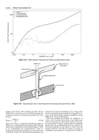
Well bore High pressure
Gas zone
Casing leak
Bad cement job
Oil zone
Figure 15.9 Gas production due to channeling behind the casing (Clark and Schultz, 1956).
terminal slip velocity. The minimum gas flow rate (in attributed to several facts including the use of drag coeffi-
MMcf/D) for a particular set of conditions (pressure and cients for solid spheres, the assumption of stagnation velo-
conduit geometry) can be calculated using Eqs. (15.23) and city, and the critical Weber number established for drops
(15.24): falling in air, not in compressed gas.
The main problem that hinders the application of
3:06pv sl A
Q gslMM ¼ (15:24) Turner et al.’s entrained drop model to gas wells comes
Tz from the difficulties of estimating the values of fluid den-
Figure 15.19 shows a comparison between the results of sity and pressure. Using an average value of gas-specific
Turner et al.’s entrained drop movement model. The map gravity (0.6) and gas temperature (120 8F), Turner et al.
shows many loaded points in the unloaded region. Turner derived an expression for gas density as 0.0031 times the
et al. recommended the equation-derived values be pressure. However, they did not present a method for
adjusted upward by approximately 20% to ensure removal calculating the gas pressure in a multiphase flow wellbore.
of all drops. Turner et al. believed that the discrepancy was