Page 209 - Petroleum Production Engineering, A Computer-Assisted Approach
P. 209

Guo, Boyun / Computer Assited Petroleum Production Engg 0750682701_chap13 Final Proof page 205  3.1.2007 9:07pm Compositor Name: SJoearun


                                                                                           GAS LIFT  13/205

                                                  Flow           selection of installation methods. Optimization of existing
                                                                 gas lift systems is left to Chapter 18.
                                                                 References
                       Gas
                                                                 brown, k.e. The Technology of Artificial Lift Methods,
                                                   Unloading Gas lift  Vol. 1. Tulsa, OK: PennWell Books, 1977.
                                                   Valve         brown, k.e. The Technology of Artificial Lift Methods,
                                                   Bottom unloading  Vol. 2a. Tulsa, OK: Petroleum Publishing Co., 1980.
                                                   Gas lift Valve  economides, m.j., hill, a.d., and ehig-economides, c.
                                                                    Petroleum Production Systems. New Jersey: Prentice
                                                Hanger Nipple for Dip  Hall PTR, 1994.
                                                tube             gilbert, w.e. Flowing and gas-lift well performance. API
                                                  Operating Chamber  Drill. Prod. Practice 1954.
                                                  Gas lift Valve   guo, b. and ghalambor, a. Natural Gas Engineering
                                                                    Handbook. Houston, TX: Gulf Publishing Co., 2005.
                                                     Packer      katz, d.l., cornell, d., kobayashi, r., poettmann, f.h.,
                                                                    vary, j.a., elenbaas, j.r., and weinaug, c.f. Handbook
                                                      Bleed Port or  of Natural Gas Engineering. New York: McGraw-Hill
                                                      Valve         Publishing Company, 1959.
                                                                 weymouth, t.r. Problems in Natural Gas Engineering.
                                                    Standing Valve
                                                                    Trans. ASME 1912;34:185.
                                                                 Problems
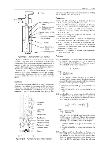
                           Figure 13.24 A sketch of an insert chamber.
                         Figure 13.24 illustrates an insert chamber. It is normally  13.1 An oil well has a pay zone around the mid-perf depth
                       used in a long open hole or perforated interval where  of 5,200 ft. The formation oil has a gravity of
                       squeezing of fluids back to formation by gas pressure is a  30 8API and GLR of 500 scf/stb. Water cut remains
                       concern. It takes the advantage of existing bottom-hole  10%. The IPR of the well is expressed as
                       pressure. The disadvantage of the installation is that the
                                                                                    p
                       chamber size is limited by casing diameter.              q ¼ Jb  p   p wf c,
                         Shown in Fig. 13.25 is a reverse flow chamber. It ensures  where
                       venting of all formation gas into the tubing string to empty  J ¼ 0:5 stb=day=psi
                       the chamber for liquid accumulation. For wells with high-    p p ¼ 2,000 psia.
                       formation GLR, this option appears to be an excellent
                       choice.                                       A 2-in. tubing (1.995-in. ID) can be set with a
                                                                     packerat200 ftabovethemid-perf.Whatisthemaximum
                                                                     expectedoilproductionratefromthewellwithcontinuous
                       Summary
                                                                     gas lift at a wellhead pressure of 200 psia if
                       This chapter presents the principles of gas lift systems and
                       illustrates a procedure for designing gas lift operations.  a. unlimited amount of lift gas is available for the
                       Major tasks include calculations of well deliverability,  well?
                       pressure and horsepower requirements for gas lift gas  b. only 1.2 MMscf/day of lift gas is available for the
                       compression, gas lift valve selection and spacing, and  well?
                                                                 13.2 An oil well has a pay zone around the mid-perf depth
                                                                     of 6,200 ft. The formation oil has a gravity of
                                                                     30 8API and GLR of 500 scf/stb. Water cut remains
                                                                     10%. The IPR of the well is expressed as
                                              Unloading                      "                   2 #
                                              Valves                               p wf      p wf
                                                                        q ¼ q max 1   0:2    0:80:2  ,
                                                                                      p p      p p
                                          Gas
                                              Operating            where
                                                                     q max ¼ 2,000 stb=day
                                              Valve
                                                                         p p ¼ 2,500 psia.
                                              Stinger tube             1
                                                                     A2 ⁄ 2 -in.tubing(2.259-in.ID)canbesetwithapacker
                                                                     at 200 ft above the mid-perf. What is the maximum
                                              Top Packer
                                                                     expected oil production rate from the well with con-
                                    Gas       Perforated Nipple      tinuous gas lift at a wellhead pressure of 150 psia if
                                              Stinger Receiver
                              Liquids         Perforated Nipple      a. unlimited amount of lift gas is available for the
                                                                       well?
                                                                     b. only 1.0 MMscf/day of lift gas is available for the
                                              Standing Valve
                                                                       well?
                                              Packer
                                                                 13.3 An oil field has 24 oil wells defined in Problem 13.1.
                                                                     The gas lift gas at the central compressor station is
                                                                     first pumped to three injection manifolds with 6-in.
                                                                     ID, 2-mile lines and then distributed to the well heads
                         Figure 13.25 A sketch of a reserve flow chamber.  with 4 in. ID, 0.5-mile lines. Given the following
   204   205   206   207   208   209   210   211   212   213   214