
Page 201 - Petroleum Production Engineering, A Computer-Assisted Approach
P. 201
Guo, Boyun / Computer Assited Petroleum Production Engg 0750682701_chap13 Final Proof page 197 3.1.2007 9:07pm Compositor Name: SJoearun
GAS LIFT 13/197
13.5.3 Valve Spacing
Various methods are being used in the industry for design-
Gas Charged ing depths of valves of different types. They are
P d the universal design method, the API-recommended
Dome
method, the fallback method, and the percent load method.
Bellows However, the basic objective should be the same:
A b
Valve Entry 1. To be able to open unloading valves with kickoff and
Ports P c injection operating pressures
2. To ensure single-point injection during unloading and
Valve normal operating conditions
Entry Ports 3. To inject gas as deep as possible
No matter which method is used, the following principles
apply:
A p
Stem and Seat . The design tubing pressure at valve depth is between gas
Choke injection pressure (loaded condition) and the minimum
tubing pressure (fully unloaded condition).
P t . Depth of the first valve is designed on the basis of kickoff
pressure from a special compressor for well kickoff oper-
ations.
Tubing . Depths of other valves are designed on the basis of
Tubing Entry Port
injection operating pressure.
. Kickoff casing pressure margin, injection operating cas-
ing pressure margin, and tubing transfer pressure mar-
gin are used to consider the following effects:
8 Pressure drop across the valve
8 Tubing pressure effect of the upper valve
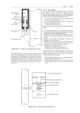
Figure 13.14 A sketch of a throttling pressure valve. 8 Nonlinearity of the tubing flow gradient curve.
The universal design method explained in this section is
valid for all types of continuous-flow gas lift valves. Still,
in the upward position. This is the open position for the different procedures are used with the universal design
pilot. The casing pressure acts to move the stem to the method, including the following:
closed position. The fluid pilot will only open when tubing
pressure acting on the pilot area is sufficient to overcome a. Design procedure using constant surface opening pres-
the casing pressure force and move the stem up to the sure for pressure-operated valves.
open position. At the instant of opening, the pilot opens b. Design procedure using 10- to 20-psi drop in surface
completely, providing instantaneous operation for inter- closing pressures between valves for pressure-operated
mittent lift. valves.
Dome (loading element)
Bellows (response element)
A b , Area of Bellows
P t S t , Spring Tension
Tubing Pressure
A p
Area of Port P c , Casing Pressure
Figure 13.15 A sketch of a fluid-operated valve.