Page 198 - Petroleum Production Engineering, A Computer-Assisted Approach
P. 198

Guo, Boyun / Computer Assited Petroleum Production Engg 0750682701_chap13 Final Proof page 194  3.1.2007 9:07pm Compositor Name: SJoearun


               13/194  ARTIFICIAL LIFT METHODS
                                                                                 P
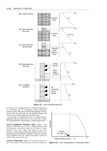
                           (a)  Initial condition                                 tbg
                                                          All valves       G s
                                                            open


                                                                                 P tbg
                           (b) Gas enters the
                               first valve
                                                          All valves
                                                            open           G f  G s


                                                                                 P tbg
                           (c) Gas enters the
                               second valve
                                                           The first
                                                            valve
                                                           begins to
                                                                             G
                                                            close             f


                           (d) Gas enters the               Valves               P tbg
                               last valve                   closed

                                                            Valve
                                                            begins         G f
                                                            to close


                                                                               P tbg
                           (e) Unloaded
                               condition
                                                           All
                                                           unloading
                                                           valves
                                                           closed
                                                                            G f


                                         Figure 13.7 Well unloading sequence.
               in continuous flow installations but is particularly important
               in intermittent gas lift installations where unbalanced
               valves are used. The spread controls the minimum amount
               of gas used for each cycle. As the spread increases, the
               amount of gas injected during the cycle increases.
                Gas passage of unbalanced valves are tubing-pressure
               dependent due to partial travel of the valve stem. Figure
               13.11 illustrates flow characteristics of unbalanced valves.
                                                          q g, scf/day
               13.5.2.1.2 Balanced Pressure Valve Figure 13.12
               depicts a balanced pressure valve. Tubing pressure does
               not influence valve status when in the closed or open
               condition. The valve opens and closes at the same
               pressure—dome pressure. Balanced pressure valves act as  Critical
               expanding orifice regulators, opening to pass any amount  flow ratio
               of gas injected from the surface and partial closing to
               control the lower gas flow rate.                                              P
                                                              Tubing Pressure, (psi)          c
               13.5.2.1.3 Pilot Valve Figure 13.13 shows a sketch of a
               pilot valve used for intermittent gas lift where a large port  Figure 13.8 Flow characteristics of orifice-type valves.
   193   194   195   196   197   198   199   200   201   202   203