
Page 200 - Petroleum Production Engineering, A Computer-Assisted Approach
P. 200
Guo, Boyun / Computer Assited Petroleum Production Engg 0750682701_chap13 Final Proof page 196 3.1.2007 9:07pm Compositor Name: SJoearun
13/196 ARTIFICIAL LIFT METHODS
defined as the tubing pressure required to open the valve
q g
Gas Flow Rate under actual operating conditions. Force balance gives
1 R
P vo ¼ P d þ S t P c , (13:44)
1 R 1 R
where P c ¼ casing pressure, psig.
R
R
is called
P c is called the C.E. and
The term
P t T.E.F. for fluid valves. With other parameters given, Eq.
1 R
1 R
Tubing Pressure Throttling depth, that is, P d ¼ (1 R)P vo S t þ RP c , in valve selection.
(13.44) is used for determining required dome pressure at
range
When a fluid valve is in its open position under operat-
ing conditions, the maximum pressure under the ball (as-
sumed to be tubing pressure) required to close the valve is
called the valve closing pressure and is expressed as
P vc ¼ P d þ S t 1 Rð Þ, (13:45)
Maximum
flow rate which is identical to that for a pressure-operated valve.
The first generation of fluid valves is a differential valve.
As illustrated in Fig. 13.16, a differential valve relies on the
difference between the casing pressure and the spring
pressure effect to open and close. The opening and closing
Casing pressures are the same tubing pressure defined as
pressure
P vo ¼ P vc ¼ P c S t : (13:46)
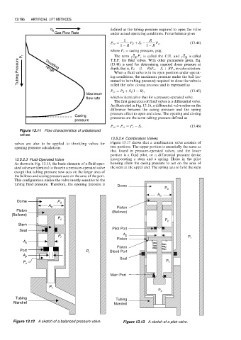
Figure 13.11 Flow characteristics of unbalanced
valves.
13.5.2.4 Combination Valves
valves are also to be applied to throttling valves for Figure 13.17 shows that a combination valve consists of
opening pressure calculations. two portions. The upper portion is essentially the same as
that found in pressure-operated valves, and the lower
portion is a fluid pilot, or a differential pressure device
13.5.2.3 Fluid-Operated Valve incorporating a stem and a spring. Holes in the pilot
As shown in Fig. 13.15, the basic elements of a fluid-oper- housing allow the casing pressure to act on the area of
ated valve are identical to those in a pressure-operated valve the stem at the upper end. The spring acts to hold the stem
except that tubing pressure now acts on the larger area of
the bellows and casing pressure acts on the area of the port.
This configuration makes the valve mostly sensitive to the
tubing fluid pressure. Therefore, the opening pressure is Dome
P d
A b
Dome P d
A b Piston
Piston (Bellows)
(Bellows)
P c
P c
Stem
Pilot Port
Seal
P t A p P t
A s Piston
Piston
Port P t Bleed Port
A p
Seal
P c P t
Main Port
P t
P c
Tubing Tubing
Mandrel Mandrel
Figure 13.12 A sketch of a balanced pressure valve. Figure 13.13 A sketch of a pilot valve.