Page 178 - Petroleum Production Engineering, A Computer-Assisted Approach
P. 178

Guo, Boyun / Computer Assited Petroleum Production Engg 0750682701_chap12 Final Proof page 174  4.1.2007 2:43pm Compositor Name: SJoearun


               12/174  ARTIFICIAL LIFT METHODS
               to be used. Select surface and subsurface equipment for the  Therefore, the selected pumping unit and rod meet well
               installation. Use a safety factor of 1.35 for the prime  load and volume requirements.
               mover power.
                                                         7. If a LUFKIN Industries C–320D–213–86 unit is
                                                           chosen, the structure unbalance is 450 lb and 4 No. 5
               Solution                                    ARO counterweights placed at the maximum position
                                                           (c in this case) on the crank will produce an effective
               1. Assuming volumetric efficiency of 0.8, the required
                                                           counterbalance load of 12,630 lb, that is,
                 pump displacement is
                                                                   (37) (96:05)
                          (600)=(0:8) ¼ 750 bbl=day:             W c        þ 450 ¼ 12,630 lb,
                                                                   (37) (111)
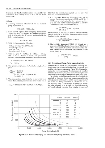
               2. Based on well depth 3,500 ft and pump displacement  which gives W c ¼ 14,075 lb. To generate the ideal counter-
                 750 bbl/day, Fig. 12.8 suggests API pump size 320 unit  balance load of C ¼ 10,327 lb, the counterweights should
                 with 84 in. stroke, that is, a pump is selected with the  be placed on the crank at
                 following designation:
                                                                    (10,327)(111)
                                                                 r ¼          (37) ¼ 31:4in:
                             C---320D---213---86                    (14,076)(96:05)
               3. Table 12.4 g suggests the following:
                                                         8. The LUFKIN Industries C–320D–213–86 unit has a
                  Tubing size: 3 in. OD, 2.992 in. ID      gear ratio of 30.12 and unit sheave sizes of 24, 30, and
                            1
                  Plunger size: 2 ⁄ 2 in.                  44 in. are available. If a 24-in. unit sheave and a 750-
                         7
                  Rod size: ⁄ 8 in.                        rpm electric motor are chosen, the diameter of the
                  Pumping speed: 18 spm                    motor sheave is
               4. Table 12.1 gives d 1 ¼ 96:05 in., d 2 ¼ 111 in., c ¼ 37 in.,  (18)(30:12)(24)
                 and h ¼ 114 in., thus c/h ¼ 0.3246. The spreadsheet  d e ¼     ¼ 17:3in:
                 program SuckerRodPumpingFlowRate&Power.xls gives        (750)
                   q o ¼ 687 bbl=day > 600 bbl/day
                  P pm ¼ 30:2hp                          12.7 Principles of Pump Performance Analysis
               5. The spreadsheet program SuckerRodPumpingLoad.xls  The efficiency of sucker rod pumping units is usually ana-
                 gives                                   lyzed using the information from pump dynagraph and
                                                         polisher rod dynamometer cards. Figure 12.9 shows a sche-
                  PRL max ¼ 16,121 lb                    matic of a pump dynagraph. This instrument is installed
                  PRL min ¼ 4,533 lb                     immediately above the plunger to record the plunger stroke
                      T ¼ 247,755 lb < 320,000 in.-lb    and the loads carried by the plunger during the pump cycle.
                      C ¼ 10,327 lb                       The relative motion between the cover tube (which is
                                                     2
                                       7
               6. The cross-sectional area of the ⁄ 8 -in. rod is 0.60 in. .  attached to the pump barrel and hence anchored to the
                                                         tubing) and the calibrated rod (which is an integral part of
                 Thus, the maximum possible stress in the sucker rod is
                                                         the sucker rod string) is recorded as a horizontal line on
                                                         the recording tube. This is achieved by having the record-
                  s max ¼ (16,121)=(0:60) ¼ 26,809 psi < 30,000 psi:
                                                         ing tube mounted on a winged nut threaded onto the
                                                         calibrated rod and prevented from rotating by means of
                       2,500
                                                                  Curve  API size  Stroke
                                                                           40
                     Pump Displacement (bbl/day)  1,500             G     320     144
                                                                                   34
                                                                    A
                       2,000
                                                                    B
                                                                                   42
                                                                           57
                                                                           80
                                                                                   48
                                                                    C
                                                                           114
                                                                                   54
                                                                    D
                                                                           160
                                                                                   64
                                                                    E
                                                                    F
                                                                                   74
                                                                           228
                       1,000
                                                                                   84
                                                                    H
                                                                           640
                        500
                          0
                           0        2,000     4,000     6,000     8,000     10,000    12,000
                                                   Pump Setting Depth (ft)
                            Figure 12.8 Sucker rod pumping unit selection chart (Kelley and Willis, 1954).
   173   174   175   176   177   178   179   180   181   182   183