
Page 248 - Materials Chemistry, Second Edition
P. 248
Groundwater Remediation 231
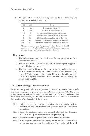
(f) The general shape of the envelope can be defined by using the
above characteristic distances:
x (ft) y (ft) Note
0 9.6 location of the first well
0 −9.6 location of the second well
−9.6 0 downstream distance (stagnation point)
0 30 sidestream distance at the line of the wells
0 −30 sidestream distance at the line of the wells
300* 60 sidestream distance far upstream of the wells
300* −60 sidestream distance far upstream of the wells
* The sidestream distance far upstream of the wells, ±60 ft, should
occur at x = ∞. A value of 300, which is 10 times the sidestream
distance at the line of wells, is used as the value of x.
Discussion:
1. The sidestream distance at the line of the two pumping wells is
twice that of one well.
2. The sidestream distance far upstream of the two pumping wells
is twice that of one well.
3. The downstream distance of the two pumping wells is the same
as that of one pumping well. The calculated downstream dis-
tance, Q/2πBu, is along the x-axis. However, the affected dis-
tances directly downstream of these two wells should be slightly
larger than Q/2πBu.
6.2.2.3 Well Spacing and Number of Wells
As mentioned previously, it is important to determine the number of wells
and their spacing in a groundwater remediation program. After the extent
of the plume as well as the direction and velocity of the groundwater flow
have been determined, the following procedure can be used to determine
the number of wells and their locations:
Step 1: Determine the groundwater pumping rate from aquifer testing
or estimate the flow rate by using information of the aquifer
materials.
Step 2: Draw the capture zone of one groundwater well (see Example
6.5 or 6.6), using the same scale as the plume map.
Step 3: Superimpose the capture-zone curve on the plume map.
Step 4: If the capture zone can completely encompass the extent of the
plume, one pumping well is sufficient. The location of the well