
Page 245 - Materials Chemistry, Second Edition
P. 245
228 Practical Design Calculations for Groundwater and Soil Remediation
(e) The general shape of the envelope can be defined by using the
given characteristic distances:
x (ft) y (ft) Note
0 0 well location
−9.6 0 downstream distance (stagnation point)
0 15 sidestream distance at the line of the well
0 −15 sidestream distance at the line of the well
150* 30 sidestream distance at far upstream of the well
150* −30 sidestream distance at far upstream of the well
*The sidestream distance at far upstream of the well, ± 30 ft, should
occur at x = ∞. A value of 150, which is ten times the sidestream dis-
tance at the line of well, is used here as the value of x.
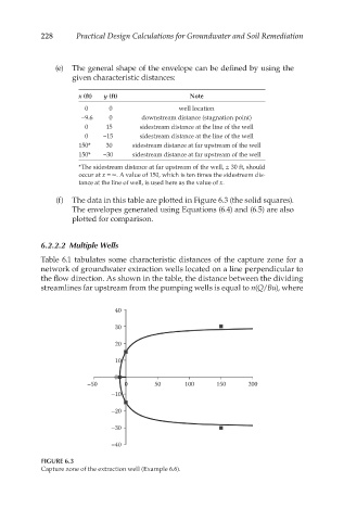
(f) The data in this table are plotted in Figure 6.3 (the solid squares).
The envelopes generated using Equations (6.4) and (6.5) are also
plotted for comparison.
6.2.2.2 Multiple Wells
Table 6.1 tabulates some characteristic distances of the capture zone for a
network of groundwater extraction wells located on a line perpendicular to
the flow direction. As shown in the table, the distance between the dividing
streamlines far upstream from the pumping wells is equal to n(Q/Bu), where
40
30
20
10
0
–50 0 50 100 150 200
–10
–20
–30
–40
FIGURE 6.3
Capture zone of the extraction well (Example 6.6).