
Page 298 -
P. 298
CHAPTER TEN
10.42
E tectrode
Dielectric
02 D Discharge gap m 03
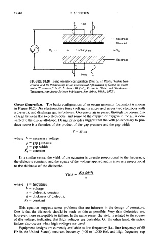
F|GURE 10.20 Basic ozonator configuration. [Source: H. Rosen, "Ozone Gen-
eration and Its Relationship to the Economical Application of Ozone in Waste-
water Treatment," in F. L. Evans lIl (ed.), Ozone in Water and Wastewater
Treatment, Ann Arbor Science Publishers, Ann Arbor, Mich., 1972.]
The basic configuration of an ozone generator (ozonator) is shown
Ozone Generation.
in Figure 10.20. An electromotive force (voltage) is impressed across two electrodes with
a dielectric and discharge gap in between. Oxygen or air is passed through the corona dis-
charge between the two electrodes, and some of the oxygen or oxygen in the air is con-
verted to the ozone allotrope. Design principles suggest that the voltage necessary to pro-
duce ozone is a function of the product of the gap pressure and the gap width.
V = Klpg
where V = necessary voltage
p = gap pressure
g = gap width
gl = constant
In a similar sense, the yield of the ozonator is directly proportional to the frequency,
the dielectric constant, and the square of the voltage applied and is inversely proportional
to the thickness of the dielectric.
Yield = K2(feV2)
d
where f = frequency
V = voltage
e = dielectric constant
d = thickness of dielectric
K2 = constant
This equation suggests some problems that are inherent in the design of ozonators.
One is that the dielectric should be made as thin as possible. Very thin dielectrics are,
however, more susceptible to failure. In the same sense, the yield is related to the square
of the voltage, indicating that high voltages are desirable. On the other hand, dielectric
failure also occurs when high voltages are used.
Equipment designs are currently available as low-frequency (i.e., line frequency of 60
Hz in the United States), medium-frequency (400 to 1,000 Hz), and high-frequency (up