
Page 477 -
P. 477
ACTIVATED CARBON PROCESSES 14.25
cannot be completely exhausted. This prevents any contaminant breakthrough into the ef-
fluent that may cause effluent water quality standards to be exceeded.
The performance of pulsed beds is affected by suspended solids or biodegradable com-
pounds that cause extensive biofilm growth on the activated carbon, so that the bed must
be backwashed. Backwashing leads to mixing of the fresh activated carbon at the top of
the bed with spent activated carbon deeper in the bed and destroys some of the benefi-
cial countercurrent effect. Additionally, some activated carbon fines may be produced dur-
ing upflow that may require removal by a subsequent process.
Another characteristic of the pulsed bed system is that a steady-state constant effluent
concentration (assuming a constant influent concentration) is achieved. In fixed beds, ef-
fluent concentration gradually increases with time.
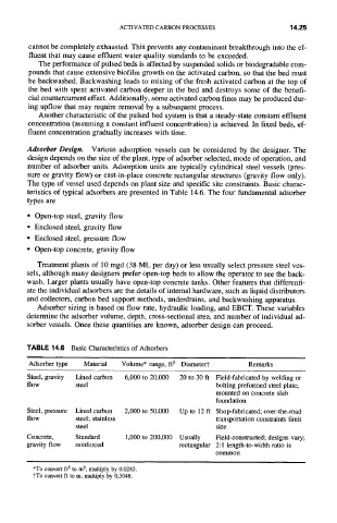
Adsorber Design. Various adsorption vessels can be considered by the designer. The
design depends on the size of the plant, type of adsorber selected, mode of operation, and
number of adsorber units. Adsorption units are typically cylindrical steel vessels (pres-
sure or gravity flow) or cast-in-place concrete rectangular structures (gravity flow only).
The type of vessel used depends on plant size and specific site constraints. Basic charac-
teristics of typical adsorbers are presented in Table 14.6. The four fundamental adsorber
types are
• Open-top steel, gravity flow
• Enclosed steel, gravity flow
• Enclosed steel, pressure flow
• Open-top concrete, gravity flow
Treatment plants of 10 mgd (38 ML per day) or less usually select pressure steel ves-
sels, although many designers prefer open-top beds to allow the operator to see the back-
wash. Larger plants usually have open-top concrete tanks. Other features that differenti-
ate the individual adsorbers are the details of internal hardware, such as liquid distributors
and collectors, carbon bed support methods, underdrains, and backwashing apparatus.
Adsorber sizing is based on flow rate, hydraulic loading, and EBCT. These variables
determine the adsorber volume, depth, cross-sectional area, and number of individual ad-
sorber vessels. Once these quantifies are known, adsorber design can proceed.
TABLE 14.6 Basic Characteristics of Adsorbers
Adsorber type Material Volume* range, ft 3 Diametert Remarks
Steel, gravity Lined carbon 6,000 to 20,000 20 to 30 ft Field-fabricated by welding or
flow steel bolting preformed steel plate;
mounted on concrete slab
foundation
Steel, pressure Lined carbon 2,000 to 50,000 Up to 12 ft
Shop-fabricated; over-the-road
flow steel; stainless
transportation constraints limit
steel size
Concrete, Standard 1,000 to 200,000 Usually
Field-constructed; designs vary;
gravity flow reinforced rectangular 2:1 length-to-width ratio is
common
*To convert ft 3 to m 3, multiply by 0.0283.
tTo convert ft to m, multiply by 0.3048.