
Page 478 -
P. 478
CHAPTER FOURTEEN
14.26
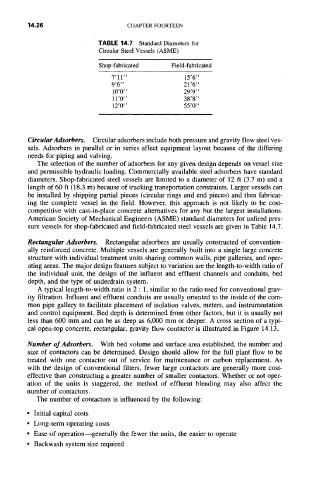
TABLE 14.7 Standard Diameters for
Circular Steel Vessels (ASME)
Shop-fabricated Field-fabricated
7'11" 15'6"
9'6" 21'6"
10'0" 29'9"
11'0" 38'8"
12'0" 55'0"
CircularAdsorbers. Circular adsorbers include both pressure and gravity flow steel ves-
sels. Adsorbers in parallel or in series affect equipment layout because of the differing
needs for piping and valving.
The selection of the number of adsorbers for any given design depends on vessel size
and permissible hydraulic loading. Commercially available steel adsorbers have standard
diameters. Shop-fabricated steel vessels are limited to a diameter of 12 ft (3.7 m) and a
length of 60 ft (18.3 m) because of trucking transportation constraints. Larger vessels can
be installed by shipping partial pieces (circular rings and end pieces) and then fabricat-
ing the complete vessel in the field. However, this approach is not likely to be cost-
competitive with cast-in-place concrete alternatives for any but the largest installations.
American Society of Mechanical Engineers (ASME) standard diameters for unfired pres-
sure vessels for shop-fabricated and field-fabricated steel vessels are given in Table 14.7.
Rectangular Adsorbers. Rectangular adsorbers are usually constructed of convention-
ally reinforced concrete. Multiple vessels are generally built into a single large concrete
structure with individual treatment units sharing common walls, pipe galleries, and oper-
ating areas. The major design features subject to variation are the length-to-width ratio of
the individual unit, the design of the influent and effluent channels and conduits, bed
depth, and the type of underdrain system.
A typical length-to-width ratio is 2 : 1, similar to the ratio used for conventional grav-
ity filtration. Influent and effluent conduits are usually oriented to the inside of the com-
mon pipe gallery to facilitate placement of isolation valves, meters, and instrumentation
and control equipment. Bed depth is determined from other factors, but it is usually not
less than 600 mm and can be as deep as 6,000 mm or deeper. A cross section of a typi-
cal open-top concrete, rectangular, gravity flow contactor is illustrated in Figure 14.13.
Number of Adsorbers. With bed volume and surface area established, the number and
size of contactors can be determined. Design should allow for the full plant flow to be
treated with one contactor out of service for maintenance or carbon replacement. As
with the design of conventional filters, fewer large contactors are generally more cost-
effective than constructing a greater number of smaller contactors. Whether or not oper-
ation of the units is staggered, the method of effluent blending may also affect the
number of contactors.
The number of contactors is influenced by the following:
• Initial capital costs
• Long-term operating costs
• Ease of operation--generally the fewer the units, the easier to operate
• Backwash system size required