
Page 69 - 15 Dangerously Mad Projects for the Evil Genius
P. 69
48 15 Dangerously Mad Projects for the Evil Genius
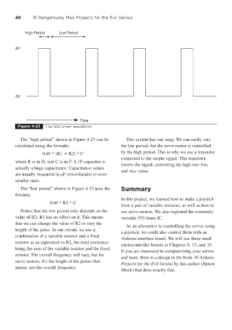
High Period Low Period
6V
0V
Time
Figure 4-23 The 555 timer waveform
The “high period” shown in Figure 4-23 can be This system has one snag: We can easily vary
calculated using the formula: the low period, but the servo motor is controlled
0.69 * (R1 R2) * C by the high period. This is why we use a transistor
connected to the output signal. This transistor
where R is in , and C is in F. A 1F capacitor is
inverts the signal, converting the high into low,
actually a huge capacitance. Capacitance values
and vice versa.
are usually measured in μF (microfarads) or even
smaller units.
The “low period” shown in Figure 4-23 uses the Summary
formula:
In this project, we learned how to make a joystick
0.69 * R2 * C
from a pair of variable resistors, as well as how to
Notice that the low period only depends on the use servo motors. We also explored the extremely
value of R2; R1 has no effect on it. This means versatile 555 timer IC.
that we can change the value of R2 to vary the
As an alternative to controlling the servos using
length of the pulse. In our circuit, we use a
a joystick, we could also control them with an
combination of a variable resistor and a fixed
Arduino interface board. We will use these small
resistor as an equivalent to R2, the total resistance
microcontroller boards in Chapters 8, 13, and 15.
being the sum of the variable resistor and the fixed
If you are interested in computerizing your servos
resistor. The overall frequency will vary, but for
and laser, there is a design in the book 30 Arduino
servo motors, it’s the length of the pulses that
Projects for the Evil Genius by this author (Simon
matter, not the overall frequency.
Monk) that does exactly that.