
Page 143 - A Comprehensive Guide to Solar Energy Systems
P. 143
142 A COmPREHEnSIVE GuIdE TO SOlAR EnERGy SySTEmS
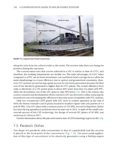
FIGURE 7.9 A typical linear Fresnel concentrator.
along the tube from the collector inlet to the outlet. The receiver tube does not change its
position during the operation.
The concentration ratio that can be achieved in a lFC is similar to that of a PTC, and
therefore, the working temperatures are similar too. The main advantages of a lFC when
compared to a PTC are its lower investment cost and better land coverage factor, while the
main disadvantage is a lower efficiency due to optical and geometrical constraints. How-
ever, lFC systems are not having a great success for electricity generation because the final
cost of the electricity generated is higher than for PTC plants. The overall efficiency from
solar to electricity of a lFC power plant is about 40% lower than that of a plant with PTC,
while the investment cost of the lFC plant is only 30% lower [15]. This is the reason why
current research and development efforts related to lFC are devoted to either reducing the
investment cost or increasing the efficiency to become more competitive with PTC systems.
Only two commercial CSTP plants with lFC were in routine operation at the end of
2016: the Puerto Herrado I and II plants located in Southern Spain with unit powers of 1.4
and 30 mW e . One lFC plant with a nominal power of 125 mW e erected in Rajasthan (India)
has been facing operational problems since its start-up in 2014. In spite of the small com-
mercial success of this CST technology, the design of several lFC plants of 50 mW e was
underway in China in 2017.
Further information about the past and current state of lFR technology is given in Ref. [16].
7.5 Parabolic Dishes
The shape of a parabolic dish concentrator is that of a paraboloid and the receiver
is placed at the focal point of the concentrator (Fig. 7.10). The most usual applica-
tion of this type of concentrator is for electricity generation using a Stirling engine