
Page 361 - A Comprehensive Guide to Solar Energy Systems
P. 361
366 A ComPRehensiVe Guide To soLAR eneRGy sysTems
5%. However, recent efforts have improved the efficiency to ∼13%. This has been possible
with the introduction of undoped ZnO instead of CdS buffer layer and coevaporation of
Na x se during the CiGs deposition. Further, bifacial CiGs solar cells with both front and
rear transparent conducting contacts were also investigated [14].
Molybdenum (Mo), grown by sputtering or e-beam evaporation is the most commonly
used electrical back contact material for CiGs solar cells. When CiGs is grown on mo an
interface layer of MoSe 2 is automatically formed which helps in ohmic transport between
CiGs and mo. Recently, alternative back contact materials have been explored but indus-
trial production is still based on mo layers. high efficiency cells have p-type Cu(in,Ga)se 2
bulk while a defect-chalcopyrite Cu(in,Ga) 3 Se 5 phase in the form of thin layer segregates
at the top surface which is n-type especially when doped by cation atoms diffusing from
the buffer layer. Several semiconductor compounds with n-type conductivity and band
gaps between 2.0 and 3.4 eV have been applied as a buffer to form a heterojunction in
CiGs solar cells. however, Cds remains the most widely investigated buffer layer. TCOs
with band gaps of above 3 eV are the most appropriate for front electrical contact due to
their optical transparency (greater than 85%) and reasonably good electrical conductivity.
Today, CiGs solar cells employ either iTo or, more frequently, RF-sputtered Al-doped Zno.
one of the breakthroughs in CiGs PV technology was the introduction of potassium [15].
These observations inspired the development of a post deposition treatment (PdT) which
led to increased efficiencies of >20% [16–18].
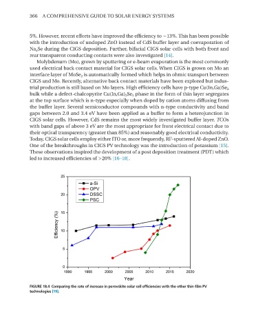
FIGURE 18.4 Comparing the rate of increase in perovskite solar cell efficiencies with the other thin-film PV
technologies [19].