
Page 145 - ARM Based Microcontroller Projects Using MBED
P. 145
7.17 PROJECT 14—POWERING LARGE LOADS—DC MOTOR CONTROL 131
7.17.3 Block Diagram
The block diagram of the project is shown in Fig. 7.76.
A load requiring large currents can be connected to a microcontroller output pin in one of
three ways: using a bipolar transistor, using a MOSFET (Metal Oxide Semiconductor Field
Effect Transistor), or using a relay.
Using a Bipolar Transistor
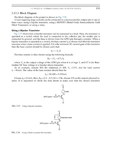
Fig. 7.77 shows how a bipolar transistor can be connected to a load. Here, the transistor is
operated as a switch where the load is connected to the collector pin, the emitter pin is
connected to ground, and the base is driven from the GPIO pin through a resistor. When a
bipolar transistor is operated as a switch, the base current I B is chosen such that the transistor
saturates when a base current is applied. If β is the minimum DC current gain of the transistor
then the base current should be chosen such that:
I B >¼ I L =β
The base resistor is then chosen using the following formula:
R B ¼ V o 0:7ð Þ=I B
where V o is the output voltage of the GPIO pin when it is at logic 1, and 0.7 is the Base-
Emitter DC bias voltage of a bipolar silicon transistor.
As an example, assume that the minimum β¼400, V o ¼3.3V, and the load current
I L ¼50mA. The value of the base resistor should then be:
I B 50=400 ¼ 0:125mA
Choose I B ¼0.2mA, then, R B ¼(3.3 0.7)/0.2¼13K, choose 12K as the nearest physical re-
sistor. It is important to check the data sheets to make sure that the chosen transistor
FIG. 7.77 Using a bipolar transistor.
FIG. 7.78 Using a diode to protect the transistor.