
Page 147 - ARM Based Microcontroller Projects Using MBED
P. 147
7.18 SUMMARY 133
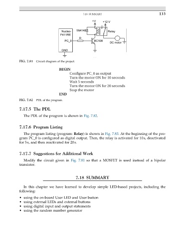
FIG. 7.81 Circuit diagram of the project.
BEGIN
Configure PC_0 as output
Turn the motor ON for 10 seconds
Wait 5 seconds
Turn the motor ON for 20 seconds
Stop the motor
END
FIG. 7.82 PDL of the program.
7.17.5 The PDL
The PDL of the program is shown in Fig. 7.82.
7.17.6 Program Listing
The program listing (program: Relay) is shown in Fig. 7.83. At the beginning of the pro-
gram PC_0 is configured as digital output. Then, the relay is activated for 10s, deactivated
for 5s, and then reactivated for 20s.
7.17.7 Suggestions for Additional Work
Modify the circuit given in Fig. 7.81 so that a MOSFET is used instead of a bipolar
transistor.
7.18 SUMMARY
In this chapter we have learned to develop simple LED-based projects, including the
following:
• using the on-board User LED and User button
• using external LEDs and external buttons
• using digital input and output statements
• using the random number generator