
Page 148 - ARM Based Microcontroller Projects Using MBED
P. 148
134 7. USING THE Mbed WITH SIMPLE PROJECTS
/***********************************************************************
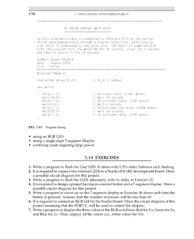
DC MOTOR CONTROL WITH RELAY
===========================
In this program a relay is connected to GPIO pin PC_0 of the nucleo-
F411RE development board through a bipolar transistor. Additionally,
a DC motor is connected to the relay pins. The motor si supplied with
+12V. The project turn the motor ON for 10 seconds, stops for 5 seconds
and then re-starst it for 20 seconds
Author: Dogan Ibrahim
Date : August 2018
File : Relay
**************************************************************************/
#include "mbed.h"
DigitalOut Relay(PC_0); // PC_0 is output
int main()
{
Relay = 1; // Activare relay (START motor)
wait(10.0); // Wait 10 seconds
Relay = 0; // de-activate relay (STOP motor)
wait(5.0); // Wait 5 seconds
Relay = 1; // Re-activate the relay (START motor)
wait(20.0); // Wait 20 seconds
Relay = 0; // De-activate relay (STOP motor)
}
FIG. 7.83 Program listing.
• using an RGB LED
• using a single-digit 7-segment Display
• switching loads requiring large power
7.19 EXERCISES
1. Write a program to flash the User LED 10 times with 0.25s delay between each flashing
2. It is required to connect two external LEDs to a Nucleo-F411RE development board. Draw
a possible circuit diagram for this project.
3. Write a program to flash the LEDs alternately with 1s delay in Exercise (2)
4. It is required to design a project having an external button and a 7-segment display. Draw a
possible circuit diagram for this project.
5. Write a program to count up on the 7-segment display in Exercise (4) above each time the
button is pressed. Assume that the number of presses will be less than 10.
6. It is required to connect an RGB LED to the Nucleo board. Draw the circuit diagram of this
project assuming that the PORT C will be used to control the display.
7. Write a program to display the three colors of the RGB as follows: Red for 5 s, Green for 3s,
and Blue for 2s. Then, display all the colors (i.e., white color) for 10s.