
Page 146 - ARM Based Microcontroller Projects Using MBED
P. 146
132 7. USING THE Mbed WITH SIMPLE PROJECTS
maximum collector current is well above the maximum required load current. It may also be
necessary to use heatsinks to protect the transistor.
It is recommended to use a freewheel diode in parallel with the load, especially with induc-
tive loads to protect the transistor when it is switched off. This is shown in Fig. 7.78.
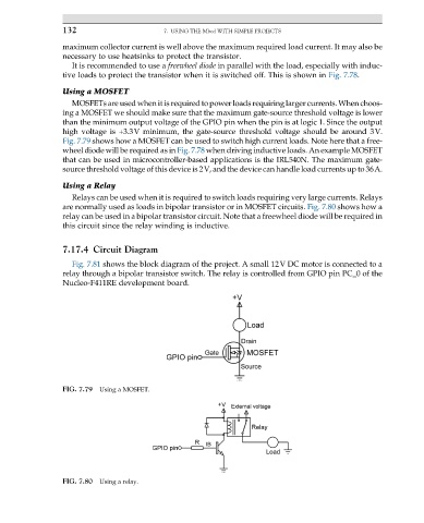
Using a MOSFET
MOSFETs are used when it is required to power loads requiring larger currents. When choos-
ing a MOSFET we should make sure that the maximum gate-source threshold voltage is lower
than the minimum output voltage of the GPIO pin when the pin is at logic 1. Since the output
high voltage is +3.3V minimum, the gate-source threshold voltage should be around 3V.
Fig. 7.79 shows how a MOSFET can be used to switch high current loads. Note here that a free-
wheel diode will be required as in Fig. 7.78 when driving inductive loads. An example MOSFET
that can be used in microcontroller-based applications is the IRL540N. The maximum gate-
source threshold voltage of this device is 2V, and the device can handle load currents up to 36A.
Using a Relay
Relays can be used when it is required to switch loads requiring very large currents. Relays
are normally used as loads in bipolar transistor or in MOSFET circuits. Fig. 7.80 shows how a
relay can be used in a bipolar transistor circuit. Note that a freewheel diode will be required in
this circuit since the relay winding is inductive.
7.17.4 Circuit Diagram
Fig. 7.81 shows the block diagram of the project. A small 12V DC motor is connected to a
relay through a bipolar transistor switch. The relay is controlled from GPIO pin PC_0 of the
Nucleo-F411RE development board.
FIG. 7.79 Using a MOSFET.
FIG. 7.80 Using a relay.