
Page 331 - ARM Based Microcontroller Projects Using MBED
P. 331
12.3 PROJECT 1—GENERATING SQUARE WAVE 317
When creating an SPI bus variable we have to specify the GPIO pins for the MOSI, MISO,
and SCLK. The default bus speed is 1MHz (1,000,000Hz), default data length is 8 bits, and the
default mode is 0. The mode depends on the requirements of the slave device and the slave
data sheet should be checked before a mode is selected.
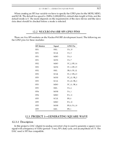
12.2 NUCLEO-F411RE SPI GPIO PINS
There are five SPI modules on the Nucleo-F411RE development board. The following are
the GPIO pins for these modules:
SPI Module Signal GPIO Pin
SPI1 SSEL PA_15
SPI1 SCLK PA_5
SPI1 MISO PA_6
SPI1 MOSI PA_7
SPI2 MISO PC_2, PB_14
SPI2 MOSI PC_3, PB_15
SPI2 SSEL PB_9, PB_12
SPI2 SCLK PC_7, PB_13
SPI3 MOSI PC_12, PB_5
SPI3 SCLK PC_10, PB_3
SPI3 MISO PC_11, PB_4
SPI3 SSEL PA_4
SPI4 MOSI PA_1
SPI4 MISO PA_11
SPI5 SCLK PB_0
SPI5 MISO PA_12
SPI5 MOSI PB_8, PA_10
SPI5 SSEL PB_1
12.3 PROJECT 1—GENERATING SQUARE WAVE
12.3.1 Description
In this project a DAC (digital-to-analog converter) chip is used to generate a square wave
signal with a frequency of 1kHz (period¼1ms), 50% duty cycle, and an amplitude of 1V. The
DAC used is SPI bus compatible.