
Page 83 - Accounting Information Systems
P. 83
54 PART I Overview of Accounting Information Systems
FI GU RE
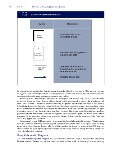
2-12 DATA FLOW DIAGRAM SYMBOL SET
Symbol Description
Input source or output
Entity
Name destination of data
N
A process that is triggered or
Process
Description supported by data
A store of data such as a
Data Store
Name transaction file, a master file,
or a reference file
Direction of data flow
be external to the organization. Entities should always be labeled as nouns on a DFD, such as customer
or supplier. Data stores represent the accounting records used in each process, and labeled arrows repre-
sent the data flows between processes, data stores, and entities.
Processes in the DFD should be labeled with a descriptive verb such as Ship Goods, Update Records,
or Receive Customer Order. Process objects should not be represented as nouns like Warehouse, AR
Dept., or Sales Dept. The labeled arrows connecting the process objects represent flows of data such as
Sales Order, Invoice, or Shipping Notice. Each data flow label should be unique—the same label should
not be attached to two different flow lines in the same DFD. When data flow into a process and out again
(to another process), they have, in some way, been changed. This is true even if the data have not been
physically altered. For example, consider the Approve Sales process in Figure 2-13, where Sales Order is
examined for completeness before being processed further. It flows into the process as Sales Order and
out of it as Approved Sales Order.
Systems analysts use DFDs extensively to represent the logical elements of the system. This technique
does not, however, depict the physical system. In other words, DFDs show what logical tasks are being
done, but not how they are done or who (or what) is performing them. For example, the DFD does not
show whether the sales approval process is separated physically from the billing process in compliance
with internal control objectives.
Entity Relationship Diagrams
An entity relationship (ER) diagram is a documentation technique used to represent the relationship
between entities. Entities are physical resources (automobiles, cash, or inventory), events (ordering