
Page 138 - Acquisition and Processing of Marine Seismic Data
P. 138
2.5 DATA ACQUISITION PARAMETERS 129
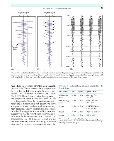
FIG. 2.80 (A) Schematic illustration of seismic trace amplitudes and dynamic range limits of a recording system. (B) In such
a narrow dynamic range recording, higher amplitudes of the reflections are clipped (arrows). (C) Four example traces with
high amplitudes at their early arrivals, which are outside the dynamic range of the recording system.
hard disks in specific BINARY data formats TABLE 2.6 Different Sample Formats Used to Store the
(Section 5.2). These seismic data samples can Seismic Data
be recorded in different sample formats repre-
Data Format Bits Bytes Signed Limits
sented by different numbers of bytes 79
(Table 2.6). These formats define how precisely IBM floating 32 Bit 4 Byte 5.4 10 to
75
point 7.2 10
the amplitude samples will be stored in the
recording media. Since the capacity of computer IEEE floating 32 Bit 4 Byte 1.18 10 38 to
38
hardware is limited, it is not possible to store point 3.37 10
and process these numbers with an extremely Integer 32 Bit 4 Byte 2,147,483,648 to
high precision. Today, seismic data is acquired +2,147,483,647
in 32-bit floating point format which uses four Integer 16 Bit 2 Byte 32,768 to +32,767
successive bytes to record each seismic ampli-
Integer 8 Bit 1 Byte 128 to +127
tude sample. In some cases, it is converted, or
compressed, into 8-bit integer format during Data is normally recorded as 32-bit floating point. From top the
the interpretation, known as scaling, to reduce bottom, the recorded data have lower resolution and dynamic range,
but occupies smaller disk space.
disk and/or memory consumption, since the