
Page 146 - Acquisition and Processing of Marine Seismic Data
P. 146
2.6 QC IN DATA ACQUISITION 137
reference axes of the vessel are defined in the d. DGPS verification: At least two simultaneous
INS (Section 2.1.7). DGPS receivers are installed on the seismic
vessels. DGPS verification is done when the
b. Streamer layout: Preparing the layout of the vessel is at dock to observe the error in the GPS
streamer(s) is a time-consuming process and solution. For DGPS receivers, normally the
should be done correctly to maintain all the horizontal positioning error is less than 1 m. In
streamers in the desired positions. Proper order to determine the accurate coordinates of
streamer steering is achieved by attaching the DGPS antennas, range and bearings to the
specific navigation instruments to the GPS antennas are calculated using a Total
streamers (Section 2.3.2). These include 3D Station located on a survey point on the quay
steering devices, devices for acoustic ranging, whose coordinates are precisely known, while
velocimeters, speed logs and compass birds. thevessel’snavigation systemlogstheantenna
The positions of these devices should be coordinates. The computed coordinates of the
accurately determined for a complete antennasare comparedtothe vessel’s readings
solution of the streamer positioning during to derive the differences in the computed and
the surveys (Figs. 2.43 and 2.44). observedcoordinates(Table2.12).Theantenna
coordinate of the DGPS is then logged for a
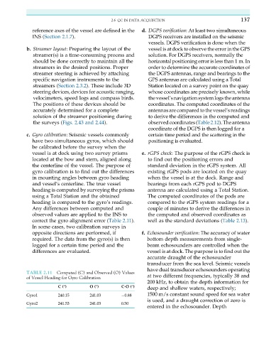
c. Gyro calibration: Seismic vessels commonly certain time period and the scattering in the
have two simultaneous gyros, which should positioning is evaluated.
be calibrated before the survey when the
vessel is at dock using two survey prisms e. rGPS check: The purpose of the rGPS check is
located at the bow and stern, aligned along to find out the positioning errors and
the centerline of the vessel. The purpose of standard deviation in the rGPS system. All
gyro calibration is to find out the differences existing rGPS pods are located on the quay
in mounting angles between gyro heading when the vessel is at the dock. Range and
and vessel’s centerline. The true vessel bearings from each rGPS pod to DGPS
heading is computed by surveying the prisms antenna are calculated using a Total Station.
using a Total Station and the obtained The computed coordinates of the pods are
heading is compared to the gyro’s readings. compared to the rGPS system readings for a
Any differences between computed and couple of minutes to derive the differences in
observed values are applied to the INS to the computed and observed coordinates as
correct the gyro alignment error (Table 2.11). well as the standard deviations (Table 2.13).
In some cases, two calibration surveys in
opposite directions are performed, if f. Echosounder verification: The accuracy of water
required. The data from the gyro(s) is then bottom depth measurements from single-
logged for a certain time period and the beam echosounders are controlled when the
differences are evaluated. vessel is at dock. The purpose is to find out the
accurate draught of the echosounder
transducer from the sea level. Seismic vessels
have dual transducer echosounders operating
TABLE 2.11 Computed (C) and Observed (O) Values
of Vessel Heading for Gyro Calibration at two different frequencies, typically 38 and
200 kHz, to obtain the depth information for
deep and shallow waters, respectively;
C(°) O (°) C-O (°)
Gyro1 240.15 241.03 0.88 1500 m/s constant sound speed for sea water
is used, and a draught correction of zero is
Gyro2 241.53 241.03 0.50
entered in the echosounder. Depth