
Page 285 - Acquisition and Processing of Marine Seismic Data
P. 285
276 5. PREPROCESSING
where g(t) is the gain function, a(t) is the input subsurface, respectively. Here, V is the velocity
seismic trace, and s(t) is the output data after of the medium, r is the distance to the source
gain recovery. point, and t is the time. Thus, the spherical diver-
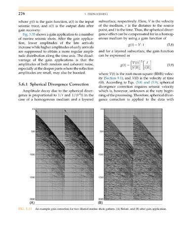
Fig. 5.35 shows a gain application to a number gence effect can be compensated for in a homog-
of marine seismic shots. After the gain applica- enous medium by using a gain function of
tion, lower amplitudes of the late arrivals gtðÞ ¼ V t (5.8)
increase while higher amplitudes of early arrivals
are suppressed to obtain a more regular ampli- and for a layered subsurface, the gain function
tude distribution along the time axis. The disad- can be expressed as
vantage of the gain applications is that the
2
amplitudes of both random and coherent noise, gtðÞ ¼ VtðÞ t (5.9)
especially at the deeper parts where the reflection V 0ðÞ t 0ðÞ
amplitudes are small, may also be boosted. where V(t) is the root-mean-square (RMS) veloc-
ity (Section 9.1), and V(0) is the velocity at time
t(0). According to Eqs. (5.8) and (5.9),spherical
5.6.1 Spherical Divergence Correction
divergence correction requires seismic velocity
Amplitude decay due to the spherical diver- which is, however, unknown at the very begin-
2
gence is proportional to 1/r and 1/(V t) in the ning of the processing. Therefore, spherical diver-
case of a homogenous medium and a layered gence correction is applied to the data with
FIG. 5.35 An example gain correction for two filtered marine shots gathers. (A) Before, and (B) after gain application.