
Page 327 - Acquisition and Processing of Marine Seismic Data
P. 327
318 6. DECONVOLUTION
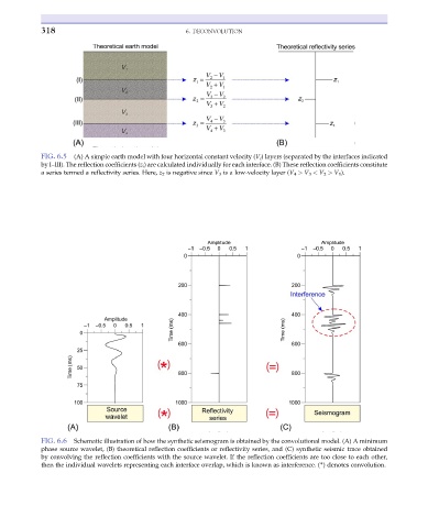
FIG. 6.5 (A) A simple earth model with four horizontal constant velocity (V i ) layers (separated by the interfaces indicated
by I–III). The reflection coefficients (z i ) are calculated individually for each interface. (B) These reflection coefficients constitute
a series termed a reflectivity series. Here, z 2 is negative since V 3 is a low-velocity layer (V 4 > V 3 < V 2 > V 1 ).
FIG. 6.6 Schematic illustration of how the synthetic seismogram is obtained by the convolutional model. (A) A minimum
phase source wavelet, (B) theoretical reflection coefficients or reflectivity series, and (C) synthetic seismic trace obtained
by convolving the reflection coefficients with the source wavelet. If the reflection coefficients are too close to each other,
then the individual wavelets representing each interface overlap, which is known as interference. (*) denotes convolution.