
Page 415 - Acquisition and Processing of Marine Seismic Data
P. 415
406 8. CDP SORT AND BINNING
different source points and are recorded at dif- indicated just below the CDP groups as color-
ferent receivers, their common property is that coded pairs of shot/receiver numbers. The num-
they are all reflected from the same subsurface ber of traces within a CDP group is known as the
location, that is, the common depth point. CDP fold and changes along the line
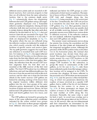
Fig. 8.1 schematically shows the relationship (Section 8.2), being maximum at the central part
between shot and CDP gathers using a 2D acqui- of the line. Geometrically, the CDP sort process
sition geometry displayed over a horizontal is to transform the data from shot records to
reflective surface for simplicity. During 2D data CDP gathers (Fig. 8.2). Shot geometry ensures
collection, both shot and receivers are moved at recording of wave fields from one specific shot
a certain distance along the line after each shot, at all available receiving channels, while CDP
defined by the shot interval. In Fig. 8.1, shot and geometry assures wave fields from various shots
receiver intervals are assumed to be equal. The to different receivers. If the reflective surfaces
number of recording channels is 6 and only 9 are not inclined, reflection hyperbolas both in
shots are displayed for simplicity in Fig. 8.1. shot and CDP gathers are similar.
The points where the rays are reflected along The seismic vessel continuously moves along
the reflective surface are indicated by small cir- the seismic line during the acquisition and the
cles, which exactly coincide with the midpoint locations of the shot points are determined by
locations of specific source and receiver pairs. the integrated navigation system. Although the
The ray path geometry suggests that more than precision of the DGPS systems today is less than
one reflection is recorded from each CDP loca- 1 m in the horizontal plane, the realized shot
tion. For instance, in Fig. 8.1, the signal reflected point locations may deviate from those pre-
from the first CDP location on the reflector ema- dicted. This results in scattering of the reflecting
nates from the first shot (black) and is recorded points around the exact CDP locations on the
at the sixth receiver of the first shot gather. Sim- reflecting subsurface (Fig. 8.3A). If we consider
ilarly, the reflection from the second CDP loca- unique CDP locations on the subsurface to
tion originates from the first shot and is group the traces in construction of the CDP
recorded at the fifth receiver of the first shot gathers, as for the case in Fig. 8.1, only those
gather. The third CDP location has two different traces reflected exactly from that unique subsur-
reflections, and each has different pathways: the face location will be assigned to the CDPs. To
first one is from the second shot (red) to the sixth overcome this situation, all traces reflected in
receiver, and the other one is from the first shot the proximity of a CDP location are incorporated
(black) to the fourth receiver. CDP gathers are (Fig. 8.3A), and the process is then termed bin-
formed by selecting (sorting) of the traces from ning, in which two parameters determine the
the original locations within different shot number of traces involved in a specific CDP
gathers into the new trace groups of the same gather, that is, width of the bin (d) and distance
reflection points, determined by the midpoint between the bin centers (r), as shown in
locations of shots and receivers. Hence, the first Fig. 8.3A. If these parameters are larger, the
and second CDP gathers have only one trace, the number of traces in the CDPs increases while
third and fourth gathers have two traces, and the total number of CDPs along the line
so on. decreases. Normally, the same value is used
The CDP gathers are formed by grouping the for both d and r to avoid trace overlap and is
traces of the same reflection point coordinate, taken as half of the group interval (Δx) in 2D sur-
indicated by the yellow colored trace groups veys. In 3D surveys, bins are two-dimensional
in Fig. 8.1. Each trace in these groups originates and their dimensions are determined by the
from different shot-receiver pairs, which are group interval and the distance between the