
Page 420 - Acquisition and Processing of Marine Seismic Data
P. 420
8.3 BINNING IN 3D 411
Fold
30 >21
16−20
28 <15
26
24
22
Inline
20
18
Fold 16
14
12
10
8
6
4
2 Crossline
5000 10000 15000 20000
(A) (B)
CDP
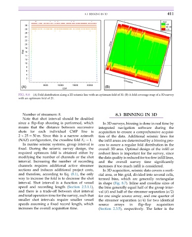
FIG. 8.6 (A) Fold distribution along a 2D seismic line with an optimum fold of 30. (B) A fold coverage map of a 3D survey
with an optimum fold of 21.
Number of streamers: 8. 8.3 BINNING IN 3D
Note that shot interval should be doubled
since a flip-flop shooting is performed, which In 3D surveys, binning is done in real time by
means that the distance between successive integrated navigation software during the
shots for each individual CMP line is acquisition to ensure a comprehensive acquisi-
2 25 ¼ 50 m. Since this is a narrow azimuth tion of the data. Additional seismic lines for
(NAZ) configuration, the crossline fold F C ¼ 1. the infill areas are determined by a binning pro-
In marine seismic systems, group interval is cess to assure a regular fold distribution in the
fixed. During the seismic survey design, the overall 3D area. Optimal design of the infill or
required optimum fold is obtained either by reshoot lines is important for the survey, since
modifying the number of channels or the shot the data quality is reduced for too few infill lines,
interval. Increasing the number of recording and the overall survey time significantly
channels requires additional active streamer increases if too much infill is considered.
sections and induces additional project costs, In 3D acquisition, seismic data covers a surfi-
and therefore, according to Eq. (8.1), the only cial area, or bin grid, divided into several cells,
way to increase the fold is to decrease the shot termed bins, which are generally rectangular
interval. Shot interval is a function of vessel in shape (Fig. 8.7). Inline and crossline sizes of
speed and recording length (Section 2.5.1.1), the bins generally equal half of the group inter-
and there is a trade-off between shot interval val (d) and half of the streamer separation (a/2)
and total operation time for the survey, such that for one single source array, and one quarter of
smaller shot intervals require smaller vessel the streamer separation (a/4) for two identical
speeds assuming a fixed record length, which source arrays in flip-flop acquisition
increases the overall acquisition time. (Section 2.3.5), respectively. The latter is the