
Page 417 - Acquisition and Processing of Marine Seismic Data
P. 417
408 8. CDP SORT AND BINNING
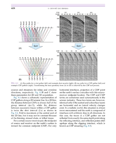
FIG. 8.2 (A) Ray paths for a shot gather (left) and example shot records (right), (B) ray paths for a CDP gather (left) and
example CDP gathers (right). Transforming the trace geometry from (A) to (B) is achieved by the CDP sort process.
sources and streamers for inline and crossline horizontal interfaces, projection of a CDP point
directions, respectively. Fig. 8.3B and C show on the earth’s surface coincides with this source-
these parameters for 2D and 3D acquisition. receiver midpoint location. The CDP and CMP
Fig. 8.4 shows a schematic representation of terms are sometimes used synonymously in the
CDP gathers along a 2D seismic line. In a 2D line, seismic industry. These two terms are, however,
the distance between CDPs is always half of the identical only if the seabed and subsurface layers
group interval (Δx/2), while the distance are horizontal and no lateral velocity changes
between successive traces within a CDP gather exist. In a realistic world, this situation is almost
is twice the shot interval (2 s) as shown in never encountered and the earth is composed of
Fig. 8.4. Fold is maximum at the central part of interfaces with arbitrary dips in all directions. In
the 2D line, but it may not be constant because this case, the traces in a CDP gather are not
of the binning, missed shots, or killed traces. reflected from exactly the same depth point along
For a certain source-receiver pair, the midpoint the reflecting interface, and reflection points shift
of source and receiver on the earth’s surface is upslope along the dipping interface, which is
termed the common midpoint (CMP). For only known as CDP smearing (Fig. 8.5).