
Page 418 - Acquisition and Processing of Marine Seismic Data
P. 418
8.2 CDP FOLD 409
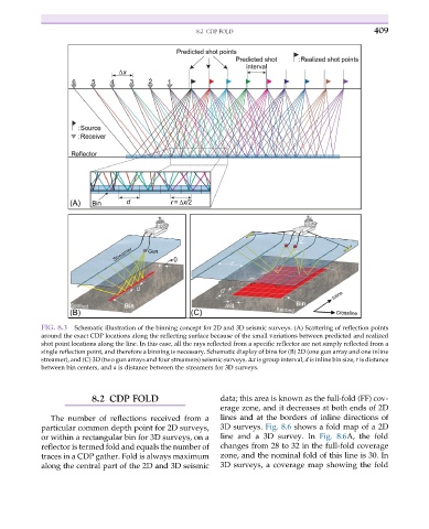
FIG. 8.3 Schematic illustration of the binning concept for 2D and 3D seismic surveys. (A) Scattering of reflection points
around the exact CDP locations along the reflecting surface because of the small variations between predicted and realized
shot point locations along the line. In this case, all the rays reflected from a specific reflector are not simply reflected from a
single reflection point, and therefore a binning is necessary. Schematic display of bins for (B) 2D (one gun array and one inline
streamer), and (C) 3D (two gun arrays and four streamers) seismic surveys. Δx is group interval, d is inline bin size, r is distance
between bin centers, and a is distance between the streamers for 3D surveys.
8.2 CDP FOLD data; this area is known as the full-fold (FF) cov-
erage zone, and it decreases at both ends of 2D
The number of reflections received from a lines and at the borders of inline directions of
particular common depth point for 2D surveys, 3D surveys. Fig. 8.6 shows a fold map of a 2D
or within a rectangular bin for 3D surveys, on a line and a 3D survey. In Fig. 8.6A, the fold
reflector is termed fold and equals the number of changes from 28 to 32 in the full-fold coverage
traces in a CDP gather. Fold is always maximum zone, and the nominal fold of this line is 30. In
along the central part of the 2D and 3D seismic 3D surveys, a coverage map showing the fold