
Page 422 - Acquisition and Processing of Marine Seismic Data
P. 422
8.3 BINNING IN 3D 413
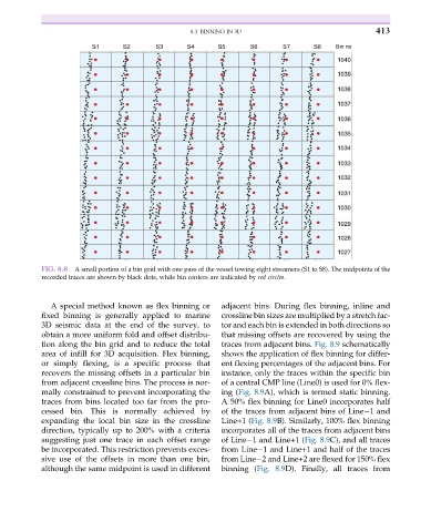
FIG. 8.8 A small portion of a bin grid with one pass of the vessel towing eight streamers (S1 to S8). The midpoints of the
recorded traces are shown by black dots, while bin centers are indicated by red circles.
A special method known as flex binning or adjacent bins. During flex binning, inline and
fixed binning is generally applied to marine crossline bin sizes are multiplied by a stretch fac-
3D seismic data at the end of the survey, to tor and each bin is extended in both directions so
obtain a more uniform fold and offset distribu- that missing offsets are recovered by using the
tion along the bin grid and to reduce the total traces from adjacent bins. Fig. 8.9 schematically
area of infill for 3D acquisition. Flex binning, shows the application of flex binning for differ-
or simply flexing, is a specific process that ent flexing percentages of the adjacent bins. For
recovers the missing offsets in a particular bin instance, only the traces within the specific bin
from adjacent crossline bins. The process is nor- of a central CMP line (Line0) is used for 0% flex-
mally constrained to prevent incorporating the ing (Fig. 8.9A), which is termed static binning.
traces from bins located too far from the pro- A 50% flex binning for Line0 incorporates half
cessed bin. This is normally achieved by of the traces from adjacent bins of Line 1 and
expanding the local bin size in the crossline Line+1 (Fig. 8.9B). Similarly, 100% flex binning
direction, typically up to 200% with a criteria incorporates all of the traces from adjacent bins
suggesting just one trace in each offset range of Line 1 and Line+1 (Fig. 8.9C), and all traces
be incorporated. This restriction prevents exces- from Line 1 and Line+1 and half of the traces
sive use of the offsets in more than one bin, from Line 2 and Line+2 are flexed for 150% flex
although the same midpoint is used in different binning (Fig. 8.9D). Finally, all traces from