
Page 423 - Acquisition and Processing of Marine Seismic Data
P. 423
414 8. CDP SORT AND BINNING
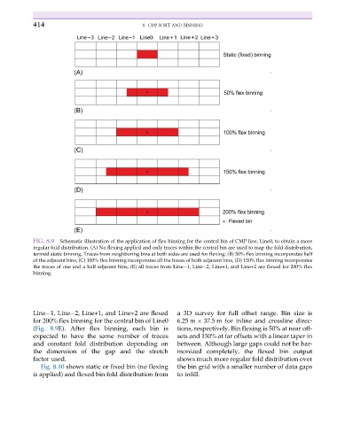
FIG. 8.9 Schematic illustration of the application of flex binning for the central bin of CMP line, Line0, to obtain a more
regular fold distribution. (A) No flexing applied and only traces within the central bin are used to map the fold distribution,
termed static binning. Traces from neighboring bins at both sides are used for flexing: (B) 50% flex binning incorporates half
of the adjacent bins, (C) 100% flex binning incorporates all the traces of both adjacent bins, (D) 150% flex binning incorporates
the traces of one and a half adjacent bins, (E) all traces from Line 1, Line 2, Line+1, and Line+2 are flexed for 200% flex
binning.
Line 1, Line 2, Line+1, and Line+2 are flexed a 3D survey for full offset range. Bin size is
for 200% flex binning for the central bin of Line0 6.25 m 37.5 m for inline and crossline direc-
(Fig. 8.9E). After flex binning, each bin is tions, respectively. Bin flexing is 50% at near off-
expected to have the same number of traces sets and 150% at far offsets with a linear taper in
and constant fold distribution depending on between. Although large gaps could not be har-
the dimension of the gap and the stretch monized completely, the flexed bin output
factor used. shows much more regular fold distribution over
Fig. 8.10 shows static or fixed bin (no flexing the bin grid with a smaller number of data gaps
is applied) and flexed bin fold distribution from to infill.